snap-on torque wrench manual pdf

This manual provides essential guidance for using Snap-on torque wrenches, ensuring precision, safety, and optimal performance. It covers calibration, maintenance, and troubleshooting for professionals and DIYers alike.

Overview of the Snap-on Torque Wrench

The Snap-on torque wrench is a precision tool designed for accurate torque application, ensuring proper fastener tightening. Built with durable materials and advanced mechanisms, it offers reliability in various industrial and automotive applications. Available in mechanical and electronic models, it features adjustable torque settings, digital displays, and angle monitoring for added accuracy. Its ergonomic design enhances user comfort and control during use. With models like the TECHANGLE, it combines torque and angular measurement, making it versatile for complex tasks. Regular calibration and maintenance are essential to maintain its precision and longevity.

Importance of Using a Torque Wrench

Using a torque wrench is crucial for ensuring accuracy and safety in fastening applications. It prevents over-tightening, which can damage threads or strip bolts, and under-tightening, leading to loose connections. Proper torque application ensures structural integrity, reduces wear and tear, and minimizes the risk of equipment failure. It is especially vital in automotive and industrial settings where precise specifications must be met. A torque wrench guarantees adherence to manufacturer guidelines, promoting reliability and safety in all operations. Always use a torque wrench to avoid potential hazards and maintain optimal performance.

Safety Precautions and Guidelines

Adhering to safety guidelines is essential when using a Snap-on torque wrench. Always handle the tool with care, avoid misuse, and wear appropriate safety gear. Follow manual instructions to prevent damage or injury.

Handling and Storage Tips

Proper handling and storage of your Snap-on torque wrench are crucial for maintaining its precision and longevity. Always clean the tool by wiping it down, avoiding immersion in liquids. Store it in a dry, secure location away from direct sunlight and extreme temperatures. Never disassemble or attempt to lubricate internal components, as this should only be done by authorized Snap-on service centers. Proper care ensures accurate torque measurements and extends the tool’s lifespan. Follow these guidelines to maintain optimal performance and safety.

Preventive Measures for Safe Operation

To ensure safe operation, always inspect the torque wrench for damage before use. Avoid applying excessive force, as this can damage the tool or lead to inaccurate measurements. Keep the work area clean and clear of obstructions to prevent accidents. Regularly check the wrench’s calibration and follow the manufacturer’s guidelines for proper use. Never use the tool near flammable materials or in hazardous environments. Proper handling and adherence to safety protocols are essential for optimal performance and operator safety.

Calibration and Maintenance

Regular calibration ensures accuracy, while proper cleaning and storage maintain tool integrity. Avoid internal lubrication and adhere to manufacturer guidelines for optimal performance and longevity.

Calibration Methods and Frequency

Calibration of Snap-on torque wrenches should be performed by authorized service centers to ensure accuracy. It is recommended to calibrate every 12 months or 5,000 cycles, whichever comes first. Proper calibration ensures adherence to ISO standards, maintaining precision in torque measurements. Regular checks and adjustments are crucial for consistent performance. Always follow the manufacturer’s guidelines for calibration procedures to avoid tool malfunction. Proper maintenance and timely calibration are essential for extending the lifespan of your Snap-on torque wrench and ensuring reliable operation.

Maintenance Tips for Precision

Regular maintenance is crucial to ensure the accuracy and longevity of your Snap-on torque wrench. Clean the tool by wiping it with a dry cloth, avoiding immersion in water. Inspect for wear and tear, especially on the handle and adjustment mechanisms. Store the wrench in a dry place, preferably in its original case. Avoid overloading the tool beyond its recommended torque range. Lubrication of internal parts is not required, as this can compromise accuracy. Always adhere to the manufacturer’s maintenance schedule for optimal performance and precision.

Operating Instructions

Always set the target torque accurately and use the correct units of measurement. Ensure the wrench is properly prepared and calibrated before application. Hold firmly, avoiding over-tightening, and follow manual guidelines for precise results.

Preparing the Torque Wrench for Use

Before using the Snap-on torque wrench, ensure it is properly calibrated and free from damage. Clean the wrench by wiping it down, avoiding immersion in liquids. Set the target torque accurately using the adjustment mechanism, ensuring the correct units of measurement are selected. Hold the wrench firmly with two hands to maintain control during operation. Always refer to the manual for specific torque values and adjustment instructions to ensure precise and safe application.

  • Verify the wrench is set to the correct mode (torque or angle).
  • Ensure the tool is not damaged or worn.
  • Apply torque smoothly and avoid sudden movements;

Proper preparation ensures accurate results and extends the tool’s lifespan.

Correct Application of Torque

Apply torque smoothly and steadily, avoiding sudden movements or jerks. Hold the wrench firmly with both hands, ensuring a secure grip on the handle. Set the target torque using the adjustment mechanism, ensuring it matches the manufacturer’s specifications. Avoid using cheater bars or excessive force, as this can damage the wrench or fastener. Verify torque settings with a manual or digital display, and recheck if adjustments are made. Proper technique prevents over-tightening and ensures accurate results.

  • Use the correct socket size for the bolt head.
  • Maintain a firm, steady grip during operation.
  • Apply torque in a consistent, controlled manner.

Regular calibration ensures precise torque application and prevents fastener damage;

Understanding Torque Measurements

Torque measurements are crucial for precise fastening, ensuring safety and preventing damage. They involve understanding units like Nm and ft-lbs. Accurate settings are vital for machinery durability.

Types of Torque Measurements

Torque measurements include peak torque, holding torque, and torque angle. Peak torque is the maximum torque applied, while holding torque maintains the fastener securely. Torque angle measures rotational movement post-tightening. These measurements ensure precise fastening, prevent over-tightening, and maintain equipment durability. Understanding these types is essential for accurate and safe torque application in various mechanical tasks. Proper measurement types help avoid damage and ensure compliance with manufacturer specifications.

Conversion and Application

Understanding torque conversion is crucial for precise application. Torque values can be converted between units like N·m, ft·lb, and in·lb using specific formulas. Always reference the manual for accurate conversions to ensure proper fastener tightening. Application involves setting the torque wrench to the desired value, aligning it correctly with the bolt, and applying steady, controlled force. Proper conversion and application prevent over-tightening, which can damage threads or strip fasteners, ensuring safe and reliable mechanical operations. Adherence to manufacturer guidelines is essential for optimal results.

Troubleshooting Common Issues

Identify issues like improper calibration, worn parts, or electronic malfunctions. Recalibrate, replace damaged components, or consult authorized service centers for professional assistance to restore accuracy and function.

Identifying Common Problems

Common issues with Snap-on torque wrenches include calibration inaccuracies, worn-out parts, and electronic malfunctions. Users may notice inconsistent torque readings, damaged handles, or failure to hold torque settings. Regular inspection can help identify these problems early. Improper storage or excessive force can also lead to mechanical failures. Additionally, ignoring maintenance schedules may result in reduced precision or complete tool malfunction. Always refer to the manual for diagnostic guidance before attempting repairs. Early detection ensures optimal performance and extends the tool’s lifespan. Proper care is essential to maintain accuracy and reliability.

Effective Solutions and Fixes

For common issues, recalibrate your Snap-on torque wrench according to the manual’s instructions. If internal mechanisms are damaged, contact authorized service centers for professional repair. Clean the tool with a dry cloth to prevent contamination. For electronic models, reset the device or update software as needed. Always refer to the manual for torque setting adjustments. Regular maintenance and proper storage can prevent malfunctions. Addressing problems promptly ensures accuracy and extends the tool’s lifespan. Professional servicing is recommended for complex repairs to maintain warranty and performance.

Repair and Service Options

For repairs, choose between DIY fixes for minor issues or professional servicing at authorized Snap-on centers for complex adjustments, ensuring warranty compliance and optimal tool performance.

DIY Repairs vs. Professional Service

DIY repairs for Snap-on torque wrenches are feasible for minor adjustments, such as cleaning or replacing worn parts. However, complex mechanical issues require professional expertise. Snap-on recommends using authorized service centers for precise recalibration and intricate repairs. Attempting advanced fixes without proper training can void the warranty or reduce tool accuracy. Always refer to the manual or contact Snap-on support for guidance on determining the appropriate repair method for your specific torque wrench model.

Authorized Service Centers

Snap-on torque wrenches should be serviced exclusively at authorized centers to ensure compliance with manufacturer standards. These centers employ certified technicians who specialize in precise recalibration, repair, and maintenance. Using unauthorized services may void the warranty and compromise tool accuracy. Always verify the credentials of service providers to maintain the reliability and performance of your Snap-on torque wrench. Regular servicing at authorized centers is crucial for extending the tool’s lifespan and ensuring optimal functionality.

Proper use, calibration, and maintenance of your Snap-on torque wrench ensure accuracy and longevity. Always refer to the manual and use authorized service centers for optimal performance.

The Snap-on Torque Wrench Manual PDF emphasizes the importance of proper tool usage, calibration, and maintenance for ensuring accuracy and safety. It highlights essential safety precautions, handling tips, and preventive measures to avoid operational risks. Regular calibration and professional servicing are stressed to maintain precision. The manual also provides clear operating instructions, troubleshooting guidance, and repair options, distinguishing between DIY fixes and professional interventions. Adhering to these guidelines ensures optimal performance, longevity, and compliance with technical specifications.

Final Tips for Optimal Use

Always calibrate your Snap-on torque wrench regularly to ensure accuracy and reliability. Store the tool in a protective case to prevent damage. Use the correct socket size for the job to avoid rounding bolts. Check for wear and tear on the wrench and replace parts as needed. Hold the wrench correctly, with a firm grip, and avoid over-tightening. Regularly clean the tool and lubricate moving parts if specified. Read the manual thoroughly and follow safety guidelines to prevent injuries. Use the wrench only for its intended purpose and refer to the manual for complex adjustments.

magic chef washing machine manual

Welcome to the Magic Chef Washing Machine Manual! This guide provides essential instructions for safe and effective use of your appliance. Discover features, installation tips, and troubleshooting solutions to enhance your experience.

Safety Precautions and Guidelines

Before using your Magic Chef Washing Machine, carefully read this section to ensure safe and proper operation. Always unplug the machine before cleaning or maintenance. Keep children away from the appliance while it is in use. Avoid using hot water for delicate fabrics, as it may cause damage. Never overload the machine, as this can lead to imbalance and poor washing performance. For your safety, avoid reaching into the washer during operation, as the moving parts may cause injury. Properly sort and prepare laundry before washing to prevent damage to clothes and the machine. Use only recommended detergents to maintain efficiency and prevent potential hazards. Follow all warnings and guidelines provided in this manual to ensure optimal performance and longevity of your appliance. Regularly inspect the power cord and plugs for damage, and replace them if necessary. In case of an emergency, turn off the machine and unplug it immediately. Always follow the manufacturer’s instructions for troubleshooting and maintenance to ensure your safety and the durability of the product.

Installation and Setup Instructions

Welcome to the installation and setup section of the Magic Chef Washing Machine Manual. Proper installation ensures safe and efficient operation of your appliance. Begin by carefully unpacking the washer and inspecting for any damage. Place the machine on a flat, stable surface to prevent vibration and imbalance. Ensure the location is well-ventilated and away from direct sunlight. Connect the power cord to a grounded electrical outlet, and ensure the voltage matches the specifications in the manual. Next, connect the water supply lines to the appropriate hot and cold water taps, making sure they are securely tightened to avoid leaks. Properly install the drain hose, ensuring it is positioned to prevent siphoning. Level the machine using the adjustable feet to maintain balance during operation. Once installed, run a test cycle without laundry to ensure everything is functioning correctly. Refer to the manual for specific instructions tailored to your model. Always follow the manufacturer’s guidelines for a safe and successful setup.

Operating Instructions

Turn off the washing machine and unplug it from the power source. Follow the instructions for draining wastewater and cleaning the pump filter. Ensure all steps are completed before restarting the appliance.

Cycle Selection and Customization

Selecting the right wash cycle is essential for optimal cleaning and fabric care. Your Magic Chef washing machine offers various cycles, including heavy-duty, delicate, and quick wash options. Choose the cycle that matches the type of laundry you are washing. For customization, you can adjust settings like water temperature and spin speed to suit your needs. Proper cycle selection ensures efficient cleaning while protecting your clothes from damage. Always refer to the care labels on your garments for specific washing instructions. By customizing your cycles, you can achieve better results and extend the life of your clothes. Explore the manual for detailed guidance on cycle options and how to tailor them for different loads.

Proper Loading Techniques

Proper loading of your Magic Chef washing machine ensures efficient cleaning and prevents damage to your clothes and the appliance. Start by separating delicate fabrics from heavier items to avoid damage. Place bulky items like towels or jeans at the bottom of the drum, while lighter fabrics like t-shirts or lingerie go on top. Avoid overloading the machine, as this can reduce cleaning effectiveness and cause wear on the washer. Leave enough space for clothes to move freely during the cycle. For optimal results, balance the load to prevent uneven distribution, which can lead to vibration during spinning. Always add detergent according to the manufacturer’s instructions to avoid overuse. Finally, check pockets for loose items like coins or keys to prevent damage during washing. By following these loading techniques, you can ensure your laundry is cleaned thoroughly and your machine operates smoothly.

Starting and Pausing the Wash Cycle

To start the wash cycle on your Magic Chef washing machine, ensure the lid is closed securely and the detergent dispenser is filled according to the manufacturer’s instructions. Next, select the desired cycle using the control panel. Choose from options like Delicate, Normal, or Bulky based on the type of laundry. Adjust settings such as water temperature and spin speed if needed. Press the Start button to begin the cycle.

If you need to pause the cycle, press the Pause/Cancel button. The machine will stop temporarily, allowing you to add or remove items. To resume, press the Start button again. Note that pausing during certain stages, such as spin, may require a brief wait before the lid can be opened safely. Always ensure the drum has stopped moving before opening the lid to avoid injury or damage. Properly managing the wash cycle ensures efficient cleaning and extends the life of your machine.

Maintenance and Cleaning Tips

Regularly clean the exterior with a soft cloth and mild soap to maintain its appearance. Leave the lid open post-use to dry the interior. Run a vinegar cleaning cycle monthly to remove buildup and freshen the machine. Inspect and replace hoses every 5 years to prevent leaks. Clean the gasket and pump filter to prevent mold and ensure proper drainage. Schedule professional maintenance annually for optimal performance. Always unplug the machine before performing any maintenance tasks to ensure safety. Adhering to these tips will prolong the lifespan and efficiency of your Magic Chef washing machine.

Cleaning the Exterior

To maintain the appearance and longevity of your Magic Chef washing machine, regular cleaning of the exterior is essential. Start by turning off the machine and unplugging it for safety. Use a soft, damp cloth to wipe down the exterior surfaces, paying attention to areas around buttons, knobs, and lids. For tougher stains or splatters, mix a small amount of mild soap with warm water and gently scrub the area. Avoid using harsh chemicals, abrasive cleaners, or rough scrubbers, as they may damage the finish. For stainless steel models, a stainless steel cleaner can be used to maintain its shine. Dry the exterior thoroughly with a clean towel to prevent water spots. Regular cleaning prevents grime and detergent residue from building up. Additionally, avoid placing the machine near direct sunlight or extreme temperatures to protect the exterior materials. By following these steps, you can keep your Magic Chef washing machine looking like new for years to come.

Cleaning the Interior

Regular cleaning of the interior is crucial to maintain your Magic Chef washing machine’s performance and hygiene. Start by leaving the lid open after a wash cycle to allow the interior to dry completely, preventing mildew and odors. For deeper cleaning, run a hot water cycle with a washing machine cleaner or 1 cup of white vinegar. Add the cleaner or vinegar directly to the drum, then select the longest and hottest cycle. If your machine has a cleaning cycle, use it monthly to remove detergent residue and debris. After cleaning, wipe the interior with a soft cloth to remove any remaining residue; For stubborn odors, sprinkle 1 cup of baking soda in the drum and run a hot water cycle. Regular interior cleaning ensures your washing machine remains fresh and efficient. Avoid using harsh chemicals, as they may damage the interior components. Always refer to the manual for specific cleaning recommendations tailored to your model.

Filter Maintenance

Regular maintenance of the filter in your Magic Chef washing machine is essential to ensure optimal performance and prevent clogs. To clean the filter, first, turn off the machine and unplug it from the power source. Locate the filter, typically found at the bottom of the machine or behind a small access panel. Remove the filter by turning it counterclockwise or sliding it out, depending on your model. Rinse the filter under warm water to remove debris, then scrub it gently with a soft brush to eliminate any residue. For stubborn buildup, soak the filter in a mixture of warm water and mild detergent for about 30 minutes. After cleaning, reinstall the filter securely to ensure proper sealing. Regular filter maintenance helps improve washing efficiency, reduces odors, and prevents damage to the machine. Refer to your manual for specific instructions tailored to your model. Clean the filter every 1-2 months or as needed.

Troubleshooting Common Issues

If your Magic Chef washing machine isn’t functioning properly, there are several common issues you can troubleshoot. First, check if the machine is properly plugged in and ensure the power outlet is working. If the machine doesn’t start, verify that the lid is closed securely and the start button has been pressed firmly. For issues with water not draining, ensure the drain hose is not kinked or clogged. If the machine is making unusual noises, inspect for loose items inside the drum or an unbalanced load. Poor washing performance could be due to incorrect detergent dosage or a clogged filter. Refer to the manual for guidance on resetting the machine or running a diagnostic cycle. Regular maintenance, such as cleaning the filter and checking for blockages, can prevent many of these issues. If problems persist, contact Magic Chef customer support for professional assistance. Always follow safety guidelines when troubleshooting to avoid injury or further damage.

Warranty Information and Support

Your Magic Chef washing machine is backed by a comprehensive warranty program designed to protect your investment. The warranty typically covers parts and labor for a specified period, depending on the model and region. To ensure your warranty remains valid, register your product online or by mail within the required timeframe. For detailed warranty terms, refer to the warranty section in this manual or visit the Magic Chef official website.

Should you encounter any issues, Magic Chef offers dedicated customer support. Contact their support team via phone, email, or live chat for assistance with troubleshooting, repairs, or general inquiries. Additionally, authorized service centers are available nationwide to provide professional help. Always keep your proof of purchase handy when requesting warranty service. For the latest updates and support resources, visit the Magic Chef website or consult this manual.

automated logic thermostat manual

Welcome to the Automated Logic Thermostat Manual, your comprehensive guide to understanding, installing, and optimizing your thermostat for advanced temperature control and energy efficiency.

Overview of Automated Logic Thermostats

Automated Logic thermostats are advanced temperature control systems designed for precision and efficiency. They offer smart automation features, seamless integration with building management systems, and user-friendly interfaces. These thermostats are ideal for commercial and industrial environments, providing real-time monitoring and adaptive temperature adjustments. With energy-saving capabilities and remote access, they ensure optimal comfort while reducing operational costs. Their compatibility with BACnet and other protocols makes them versatile for various HVAC setups. Automated Logic thermostats are known for their reliability, scalability, and ability to adapt to diverse environmental conditions. By combining cutting-edge technology with intuitive controls, they represent a modern solution for intelligent building management systems.

Importance of Proper Thermostat Installation and Configuration

Proper installation and configuration of your Automated Logic thermostat are crucial for optimal performance and efficiency. Incorrect setup can lead to temperature inaccuracies, reduced system lifespan, and higher energy costs. A well-installed thermostat ensures precise temperature control, enhancing comfort and operational efficiency. It also enables seamless integration with building automation systems, allowing for advanced features like smart scheduling and remote monitoring. Additionally, correct configuration is essential for accessing energy-saving modes and maintaining system reliability. Improper installation can void warranties and compromise safety features. Therefore, following the manufacturer’s guidelines and seeking professional assistance when needed is highly recommended to ensure your thermostat operates at its full potential and meets your specific environmental requirements effectively.

Installation and Setup Guide

This section provides a detailed guide for installing and setting up your Automated Logic thermostat, ensuring proper functionality and integration with your HVAC system.

Pre-Installation Requirements and Tools Needed

Before installing your Automated Logic thermostat, ensure you have the necessary tools and meet the system requirements. Required tools include a screwdriver, wire strippers, and a voltage tester. Verify that your HVAC system is compatible with the thermostat model. Turn off the power to the HVAC system at the circuit breaker before starting. Familiarize yourself with the wiring diagram provided in the manual to avoid errors. Ensure the thermostat’s mounting location is accessible and within the recommended temperature range. Gather all components, including the thermostat, mounting plate, and wiring connectors. Double-check the system’s voltage requirements to prevent damage. Proper preparation ensures a smooth and safe installation process. Follow all safety guidelines to avoid electrical hazards. Plan the installation steps in advance to minimize downtime.

Step-by-Step Installation Process

Begin by mounting the thermostat plate to the wall, ensuring it is level and securely fastened. Carefully connect the wires to the corresponding terminals, referring to the wiring diagram for accuracy. Attach the thermostat to the mounting plate, making sure it clicks into place. Restore power to the HVAC system and test the thermostat by adjusting the temperature settings. Verify proper operation by checking heating, cooling, and fan functions. Use a voltage tester to ensure no live wires are exposed during the process. Label the wires before disconnecting them to simplify reconnection. If unsure, consult the manual or seek professional assistance. Follow these steps carefully to ensure a safe and successful installation. Proceed to the initial configuration once the installation is complete.

Initial Configuration and Setup

After installation, power on the thermostat and follow the on-screen prompts to begin configuration. Set the current date, time, and preferred temperature units (Fahrenheit or Celsius). Navigate through the menu to configure HVAC system settings, such as heating and cooling type, fan operation, and temperature range limits. Set your desired default temperature and schedule if using smart scheduling features. Ensure the thermostat is connected to your building automation system if applicable. Refer to the manual for specific instructions on integrating with WebCTRL or other systems. Test the thermostat by adjusting settings and verifying HVAC responses. Save all configurations to ensure they are retained. If issues arise, reset the thermostat or consult the troubleshooting section for assistance. Proper setup ensures optimal performance and energy efficiency.

Advanced Features of Automated Logic Thermostats

Automated Logic Thermostats offer advanced features like smart scheduling, integration with building automation systems, and energy-saving modes to optimize heating and cooling efficiency.

Smart Scheduling and Temperature Automation

Automated Logic Thermostats feature advanced smart scheduling and temperature automation, allowing users to create custom temperature profiles tailored to their daily routines. This functionality ensures optimal comfort while minimizing energy consumption. The thermostats can be programmed via a user-friendly interface, either through a web portal or a mobile app, enabling seamless adjustments from anywhere. The system also integrates with external sensors and building automation systems to adapt to environmental changes automatically. By learning occupancy patterns and preferences over time, the thermostat can anticipate and adjust temperatures accordingly. Additionally, geofencing capabilities allow the thermostat to respond to the user’s location, further enhancing energy efficiency. These features make it easier to maintain a consistent and energy-efficient indoor climate without manual intervention.

Integration with Building Automation Systems

Automated Logic Thermostats seamlessly integrate with building automation systems (BAS), enabling comprehensive control over environmental conditions. This integration allows for centralized monitoring and management of temperature, humidity, and energy usage across multiple zones. The thermostat communicates with BAS through protocols like BACnet or Modbus, ensuring compatibility with existing infrastructure. By consolidating controls, facility managers can optimize energy efficiency, reduce operational costs, and improve occupant comfort. Real-time data from the thermostat is fed into the BAS, enabling advanced analytics and automated responses to system conditions. This integration also supports remote access and diagnostics, simplifying maintenance and troubleshooting. As a result, the thermostat becomes a key component in achieving a fully integrated and intelligent building management system.

Energy Efficiency and Cost-Saving Features

Automated Logic Thermostats are designed with cutting-edge energy efficiency features to minimize energy consumption while maintaining optimal comfort. The thermostat includes smart scheduling, allowing users to pre-set temperature adjustments based on occupancy patterns, reducing unnecessary heating or cooling. Energy-saving modes optimize performance during off-peak hours, ensuring lower utility bills. Additionally, the thermostat’s advanced algorithms learn the building’s thermal characteristics, adapting heating and cooling cycles to avoid excessive energy use. Remote access via the BAS integration enables real-time monitoring and adjustments, further enhancing energy management. These features not only reduce operational costs but also contribute to environmental sustainability by lowering overall energy consumption. By leveraging these technologies, users can achieve significant cost savings while maintaining a comfortable and efficient environment.

Troubleshooting Common Issues

Troubleshooting your Automated Logic Thermostat involves identifying error messages, checking connectivity, and verifying temperature settings. Use diagnostic tools to resolve malfunctions and ensure proper system operation.

Identifying and Resolving Connectivity Problems

Connectivity issues with your Automated Logic Thermostat can disrupt its performance. Common problems include lost network connections, faulty wiring, or outdated firmware. Ensure the thermostat is properly linked to your building automation system, such as BACnet, and that all physical connections are secure. Power cycling the device often resolves temporary glitches. Check network settings and verify that the thermostat is configured correctly within your system. For advanced troubleshooting, consult the error codes provided by the thermostat or use diagnostic tools to pinpoint the issue. Regularly updating firmware and ensuring compatibility with your automation system can prevent recurring connectivity problems. Addressing these issues promptly ensures uninterrupted climate control and energy efficiency.

Addressing Temperature Control Malfunctions

Temperature control malfunctions in your Automated Logic Thermostat can lead to discomfort and energy waste. Start by verifying the setpoint temperature and ensuring it matches your desired settings. Check the thermostat’s sensors for accuracy, as faulty readings can cause incorrect heating or cooling. If the system fails to respond, inspect the wiring and connections to the heating or cooling equipment. Ensure the thermostat is properly calibrated and that all valves or dampers are functioning. In cases of extreme temperature swings, adjust the differential settings to stabilize the environment. Regular maintenance, such as cleaning sensors and updating software, helps prevent malfunctions. Always refer to the error codes for specific guidance, and consult a professional if issues persist.

Understanding Error Codes and Solutions

Automated Logic Thermostats use error codes to indicate system issues, helping users quickly identify and resolve problems. Common codes like E1 or E2 often relate to sensor malfunctions or communication failures. Always check the thermostat’s display for specific codes and refer to the manual for detailed explanations. For example, an E1 error may indicate a faulty temperature sensor, requiring calibration or replacement. If the issue persists, restart the system or reset the thermostat. For connectivity errors, ensure all wires are secure and the network connection is stable. If troubleshooting fails, contact a certified technician. Regularly updating firmware and ensuring proper installation can prevent many error code occurrences. Familiarizing yourself with these codes ensures efficient troubleshooting and optimal system performance.

Best Practices for Maintenance and Optimization

Regularly clean sensors, update firmware, and calibrate settings to ensure peak performance. Schedule annual professional inspections to maintain efficiency and extend system lifespan.

Regular Maintenance Tips for Optimal Performance

Regular maintenance is crucial for ensuring your Automated Logic thermostat operates efficiently. Start by cleaning the thermostat’s sensors and display regularly to prevent dust buildup, which can interfere with accurate temperature readings. Next, check and replace the batteries annually if your model requires them to avoid sudden system failures. Additionally, inspect the wiring connections to ensure they are secure and free from damage. Schedule a professional inspection at least once a year to verify that the system is calibrated correctly and functioning as intended. Finally, keep the thermostat away from direct sunlight and heat sources, as this can affect its performance and lead to incorrect temperature readings. By following these simple maintenance tips, you can extend the lifespan of your thermostat and ensure optimal performance year-round.

Upgrading Firmware and Software

Upgrading your Automated Logic thermostat’s firmware and software ensures access to the latest features, improvements, and security patches. Always check the manufacturer’s website for updates and follow the provided instructions carefully. Before initiating an update, backup your current configuration to prevent data loss. Use a wired connection for a stable update process, and avoid interrupting the power supply during the upgrade. Once the update is complete, verify the new version is installed correctly and test all functionalities to ensure everything works as expected. Regular updates are essential for maintaining optimal performance and compatibility with integrated systems. Schedule updates during periods of low usage to minimize disruptions. By keeping your thermostat up to date, you ensure reliable operation and benefit from the newest advancements in automation technology.

Optimizing Settings for Specific Environments

Optimizing your Automated Logic thermostat settings for specific environments ensures maximum comfort and efficiency. For commercial spaces, adjust temperature ranges and occupancy schedules to match workflow patterns. In residential settings, prioritize comfort during peak usage hours while reducing energy consumption during inactive periods. Humidity control is crucial in coastal or high-moisture areas to prevent condensation and maintain indoor air quality. Use the thermostat’s adaptive learning feature to automatically adjust based on historical data and user preferences. Fine-tune heating and cooling curves for precise temperature control, and enable geofencing to synchronize with your location. For energy-intensive environments, activate demand response features to reduce peak load. Regularly review and update settings to adapt to seasonal changes or occupancy variations, ensuring your system performs optimally in any condition.

miro humidifier manual

Welcome to the Miro Humidifier Manual! This guide provides essential information for safe and optimal use of your device. Read carefully to ensure proper operation and maintenance.

Overview of the Miro Humidifier

The Miro Humidifier is an advanced ultrasonic device designed to enhance indoor air quality by releasing a fine‚ cool mist. It features smart connectivity options‚ allowing users to control it via voice commands or smart home systems. Compact and energy-efficient‚ the humidifier is ideal for maintaining optimal humidity levels in homes. Models like Miro-NR07SR‚ NR07BR‚ and NR07GR offer versatile solutions for various spaces.

Importance of Reading the Manual

Reading the Miro Humidifier Manual is crucial for safe and effective operation. It provides detailed instructions‚ safety guidelines‚ and troubleshooting tips to ensure optimal performance. Understanding the device’s features‚ maintenance requirements‚ and warranty conditions helps maximize its lifespan. By following the manual‚ users can avoid potential issues and enjoy a healthier indoor environment with proper humidity control.

Components and Accessories

The Miro Humidifier comes with essential components and accessories‚ including the main unit‚ water bowl‚ control panel‚ filters‚ and power adapter‚ ensuring efficient operation and maintenance.

Parts Included in the Box

The Miro Humidifier package includes the main unit‚ water bowl‚ control panel‚ filters‚ and power adapter. Additional accessories like a user manual and warranty card are also provided. Ensure all components are included before assembly for proper functionality and to avoid missing parts. Refer to the manual for a detailed inventory of included items and their purposes.

Understanding the Control Panel

The control panel includes a power button‚ mist level adjustment‚ and night mode. LED indicators display water level and filter status. Use these buttons to customize settings and monitor the humidifier’s operation effectively.

Assembly and Setup

Carefully unpack the Miro humidifier and all accessories. Assemble the parts according to the instructions. Place the water bowl correctly to ensure efficient operation.

Unpacking and Preparing the Humidifier

Start by carefully unpacking the Miro humidifier from its box. Place all components on a flat‚ stable surface. Ensure no parts are damaged during unpacking. Check for all included accessories‚ such as the water bowl and power cord. Before first use‚ rinse the water bowl with clean water and dry it thoroughly. This ensures proper function and hygiene.

Step-by-Step Assembly Instructions

Begin by aligning the water bowl with the main unit‚ ensuring it clicks securely into place. Next‚ attach the humidification module by gently pushing it until it fits snugly. Connect the power cord to the main unit and plug it into a nearby outlet. Finally‚ adjust the control panel settings according to your preferences. Refer to the manual for a detailed diagram if needed.

Filling and Maintaining the Water Tank

Regularly refill the water tank with clean‚ filtered water to ensure optimal performance. Always use distilled or filtered water to prevent mineral buildup and maintain hygiene.

How to Fill the Water Bowl

To fill the water bowl‚ ensure it is placed on a flat‚ stable surface. Use distilled or filtered water to prevent mineral buildup. Avoid overfilling‚ as this may cause leakage during operation. Align the water bowl securely with the main unit. For optimal performance‚ consider using the Miro filter to purify the water before filling.

Recommended Water Quality and Filters

For optimal performance‚ use distilled or filtered water to minimize mineral buildup. The Miro filter is recommended to purify water before use‚ especially if tap water is hard or contains impurities. Avoid using unfiltered tap water‚ as it may cause scaling and affect humidity output. Regularly cleaning the filter ensures efficient operation and maintains hygiene.

Operating the Miro Humidifier

Welcome to the operating section of the Miro Humidifier Manual. Learn how to turn on‚ adjust settings‚ and utilize smart features like voice commands for seamless control. Follow these steps to ensure optimal performance and customize humidity levels according to your preferences. Refer to the manual for detailed instructions on operation and troubleshooting.

Turning On and Adjusting Humidity Levels

To start the Miro Humidifier‚ press the power button until the indicator lights up. Use the control panel or remote to adjust humidity levels. Set your desired percentage using the touchscreen or voice commands. The device will automatically maintain the selected humidity. For optimal performance‚ ensure the water tank is filled and the filter is clean. Refer to the manual for detailed guidance on operation and customization.

Understanding the Humidification Module

The Miro Humidification Module uses ultrasonic technology to generate a fine mist‚ ensuring efficient and quiet operation. It’s designed to maintain your desired humidity levels accurately. The module features indicators for low water and cleaning needs‚ ensuring smooth performance. Regular maintenance is essential for optimal functionality. Refer to the manual for detailed care instructions.

Safety Precautions and Warnings

Important Safety Guidelines: Always read the manual thoroughly before use. Keep the humidifier out of reach of children and pets. Avoid placing it near flammable materials or water sources. Ensure proper electrical connections and avoid using damaged cords. Never submerge the device in water or expose it to excessive moisture. Use only distilled or filtered water to prevent mineral buildup and bacterial growth. Regularly clean and descale the unit to maintain hygiene and efficiency. Do not operate the humidifier if it malfunctions or leaks. Always unplug the device before cleaning or performing maintenance. Follow all warnings and guidelines to ensure safe and effective operation.

Important Safety Guidelines

Safety First: Always read the manual before use. Keep the humidifier away from children and pets. Avoid placing it near open flames or flammable materials. Use only distilled or filtered water to prevent mineral buildup. Regularly clean and descale the unit to maintain hygiene. Do not submerge the device in water or operate it if damaged. Ensure proper ventilation in the room. Unplug the humidifier before cleaning or maintenance. Follow all guidelines to ensure safe operation and longevity of the device. Refer to the manual for detailed precautions and warnings to avoid accidents and ensure optimal performance. Always prioritize safety to protect yourself and others while using the Miro Humidifier.

Handling and Placement Recommendations

Place the humidifier on a stable‚ flat surface‚ avoiding carpets or wooden furniture to prevent water damage. Ensure it’s at least 12 inches away from walls to allow proper air circulation. Keep it out of direct sunlight to prevent overheating. Use a soft cloth when moving to avoid scratches. Avoid placing near open flames or heat sources. Regularly clean the area around the humidifier to prevent mold growth. Ensure the surface is level to maintain balance. Check the placement periodically to ensure optimal performance and safety.

Troubleshooting Common Issues

Identify common issues like low humidity output or device malfunction. Check water levels‚ filters‚ and power connections. Refer to the troubleshooting section for detailed solutions and maintenance tips.

Identifying and Solving Operational Problems

Common issues include low humidity output or device malfunction. Check the water level and refill if necessary. Ensure the filter is clean or replace it if dirty. Verify power connections and reset the device if needed. Refer to the indicator lights for specific error codes‚ such as “REFILL” or “FILTER‚” and follow the troubleshooting steps provided in this manual to resolve issues effectively.

Understanding Indicator Lights and Alarms

The Miro Humidifier features indicator lights to signal various statuses. The “REFILL” light illuminates when the water level is low‚ accompanied by an audible alarm. The “FILTER” light indicates when the filter needs cleaning or replacement. Other lights may signal power status or operational modes. Refer to this manual for a detailed explanation of all indicators and alarms to ensure proper functionality and maintenance of your device.

Warranty and Support Information

Your Miro Humidifier is backed by a comprehensive warranty. For details on warranty coverage and conditions‚ refer to the dedicated section in this manual. Contact customer support for assistance with any inquiries or issues‚ ensuring optimal performance and longevity of your device.

Warranty Coverage and Conditions

Your Miro Humidifier is protected under a limited warranty covering manufacturing defects for a specified period. The warranty applies to the original purchaser and is non-transferable. Damage from misuse‚ improper maintenance‚ or unauthorized repairs voids the warranty. For detailed terms and conditions‚ refer to the warranty section in this manual. Keep your proof of purchase for warranty claims and support inquiries.

Contacting Customer Support

For inquiries or assistance‚ contact Miro Customer Support via email at support@miro.com or call 1-800-MIRO-CARE. Visit the official website for live chat options and additional resources. Ensure to have your product serial number ready for efficient support. For regional contact details‚ refer to the support section on the Miro website.

Smart Features and Connectivity

The Miro Humidifier seamlessly integrates with smart home systems‚ enabling voice control via Ok Google and Amazon Alexa. Easily manage settings through the Miro app for remote operation and scheduling.

Connecting to Smart Home Systems

The Miro Humidifier is designed to integrate seamlessly with popular smart home systems. Compatible with Amazon Alexa and Google Assistant‚ it allows voice command operation. Simply link the device to your smart speaker for hands-free control. Additionally‚ the Miro app enables remote monitoring‚ scheduling‚ and adjustments‚ ensuring convenient management of humidity levels from your smartphone; This feature enhances usability and modernizes your home environment.

Using Voice Commands for Operation

The Miro Humidifier supports voice commands through integration with Amazon Alexa and Google Assistant. Users can control humidity levels‚ turn the device on/off‚ and adjust settings hands-free. For example‚ say‚ “Set the living room humidifier to 50%” or “Turn off the Miro Humidifier.” This feature enhances convenience and modernizes your smart home experience‚ allowing seamless control without manual adjustments. Use voice commands for effortless operation and tailored comfort.

Cleaning and Maintenance Tips

Regularly clean the Miro Humidifier to prevent mold and mineral buildup. Use distilled water and descale every 1-2 months for optimal performance and hygiene. Always follow manual guidelines for cleaning procedures to ensure longevity and efficiency of your device.

Regular Cleaning Schedule

For optimal performance‚ clean your Miro Humidifier weekly. Wipe the exterior with a soft cloth and mild detergent. Soak and rinse the water bowl and humidification module in warm water. Every 1-2 months‚ descale using a vinegar solution or a descaling product. Check for mineral buildup regularly and clean the filter as recommended. Always follow the manual for detailed cleaning instructions to maintain efficiency and hygiene. Regular maintenance ensures long-lasting operation and prevents mold growth‚ keeping your humidifier in excellent condition for consistent performance.

Deep Cleaning and Descale Processes

For deep cleaning‚ mix 1 part white vinegar with 2 parts water in the tank. Let it soak for 30 minutes‚ then scrub and rinse thoroughly. Descaling is essential every 1-2 months using a descaling solution or vinegar. Soak the humidification module in the solution for 10-15 minutes‚ then rinse. Regular descaling prevents mineral buildup and ensures efficient operation. Always dry the unit after cleaning to prevent mold growth. Follow these steps to maintain your humidifier’s performance and longevity.

Replacing Parts and Accessories

Replace filters every 1-3 months or as indicated by reduced performance. Use genuine Miro parts for optimal function. Check warranty for covered replacements and contact support for assistance.

When to Replace Filters and Other Parts

Replace the filter every 1-3 months or when performance decreases. Check for visible wear or damage. Cleanable parts should be washed regularly‚ but replace if they show signs of deterioration. Refer to the manual for specific guidelines on replacement intervals to maintain efficiency and ensure your humidifier functions properly. Always use genuine Miro parts for optimal performance.

Ordering Genuine Miro Replacement Parts

To ensure optimal performance‚ order genuine Miro replacement parts from authorized dealers or the official website. Verify the model number (e.g.‚ NR07SR‚ NR07BR) before purchasing. Genuine parts are designed to maintain your humidifier’s efficiency and safety. Avoid third-party alternatives to prevent potential damage or voiding your warranty.

Optimizing Humidifier Performance

To maximize your Miro Humidifier’s efficiency‚ use distilled water and clean the filter regularly. Adjust settings based on room size and humidity needs. Ensure proper placement for even moisture distribution. Regularly descale and maintain the unit to prevent mineral buildup. By following these tips‚ you can enhance performance and extend the lifespan of your humidifier.

Long-Term Care for Your Miro Humidifier

For long-term care‚ regularly clean and descale your Miro Humidifier to prevent mineral buildup. Replace filters as recommended to ensure optimal performance. Store the unit in a dry place during off-seasons and check for firmware updates. Proper maintenance will extend the lifespan and keep your humidifier functioning efficiently. Always use genuine Miro parts for replacements to maintain warranty and performance quality.

aprilaire 400 humidifier installation manual

This manual provides essential guidance for installing the Aprilaire 400 humidifier, ensuring proper setup and operation. It covers installation steps, safety guidelines, and maintenance tips.

1.1 Overview of the Aprilaire 400 Humidifier

The Aprilaire 400 humidifier is a high-efficiency, whole-house solution designed to maintain optimal humidity levels. It can be installed on either the supply or return plenum of a forced air system, offering flexibility. Compact in size, it operates quietly and efficiently, providing consistent humidity without excessive water usage. The unit is reversible, accommodating right or left-hand bypass connections. Its design ensures minimal water waste and energy consumption, making it an eco-friendly choice for homeowners seeking precise humidity control and improved indoor air quality.

1.2 Importance of Proper Installation

Proper installation of the Aprilaire 400 humidifier is crucial for ensuring optimal performance, safety, and energy efficiency. Incorrect installation can lead to poor humidity control, increased energy bills, and potential damage to the unit or HVAC system. Following the manufacturer’s guidelines ensures the humidifier operates safely and efficiently, maintaining desired humidity levels without excessive water usage. Improper installation may also void the warranty, making it essential to adhere to the provided instructions. Correct setup guarantees reliable operation and extends the lifespan of the humidifier, ensuring it meets your home’s humidity needs effectively.

Pre-Installation Considerations

Before installation, review the manual, ensure compatibility with your HVAC system, and prepare all necessary tools and materials for a smooth setup process.

2.1 Understanding the System Requirements

Understanding the system requirements for the Aprilaire 400 humidifier ensures compatibility with your HVAC setup. The unit can be installed on either the supply or return plenum, offering flexibility. It requires a 24VAC transformer and proper drainage. Ensure your system meets these specifications before proceeding to avoid installation issues. Proper alignment with your HVAC system’s operation is crucial for optimal performance and humidity control.

2.2 Gathering Necessary Tools and Materials

To ensure a smooth installation, gather all required tools and materials beforehand. These include a drill, screwdrivers, wrenches, and fasteners. The installation template provided with the humidifier is essential for accurate mounting. Additionally, ensure you have the bypass duct, water panel, and 24VAC transformer. Proper materials like foam tape and insulation may be needed to maintain system efficiency. Having all components ready will prevent delays and ensure the installation process is completed efficiently and correctly.

Key Components of the Aprilaire 400 Humidifier

The Aprilaire 400 includes a humidifier unit, bypass duct, water panel, and control system. These components work together to efficiently humidify your home’s air.

3.1 Humidifier Unit and Accessories

The Aprilaire 400 humidifier unit is designed for efficient operation, featuring a compact design that integrates seamlessly with HVAC systems. The unit measures 15 x 14.375 x 10 inches, making it suitable for various installation scenarios. It includes essential accessories like the bypass duct, water panel, and mounting hardware. The humidifier unit is reversible, allowing for flexible installation on either the supply or return plenum. Accessories such as the water panel ensure optimal moisture evaporation, while the bypass duct facilitates airflow. Proper installation of these components is crucial for maintaining energy efficiency and consistent humidity levels.

3.2 Bypass Duct and Water Panel

The bypass duct is a critical component that directs airflow through the humidifier, ensuring efficient moisture distribution. It is reversible, accommodating both right-hand and left-hand configurations. The water panel, located inside the humidifier, is designed to maximize water evaporation. It captures excess water in a reservoir, enhancing efficiency. Proper alignment and installation of these components are essential for optimal performance. The bypass duct and water panel work together to deliver precise humidity control, ensuring consistent comfort in your home.

Installation Steps

Follow detailed instructions for preparing the site, mounting the humidifier, connecting the bypass duct, and wiring the control for a successful setup and operation.

4.1 Preparing the Installation Site

Before installation, ensure the site is clean, dry, and accessible. The Aprilaire 400 can be installed on either the supply or return plenum. Measure the space to accommodate the unit’s dimensions (15 x 14.375 x 10 inches). Ensure proximity to a water supply and drainage system. Use the provided installation template to mark the plenum accurately for mounting holes. Verify that the area is free from obstructions and offers adequate clearance for maintenance. Proper preparation ensures a smooth and successful installation process.

4.2 Mounting the Humidifier on the Plenum

Mount the Aprilaire 400 humidifier on the plenum, ensuring it is level and securely fastened. The unit can be installed on either the supply or return plenum and is reversible for right or left-hand bypass connections. Use the provided installation template to mark the mounting holes accurately. Align the humidifier with the marked holes and secure it using the recommended screws. Ensure the bypass duct connection is properly positioned and aligned before tightening. Double-check that the unit is firmly attached to prevent vibration and ensure efficient operation.

4.3 Connecting the Bypass Duct

The bypass duct connects the humidifier to your HVAC system, ensuring proper humidity distribution. Attach one end of the 6-inch insulated duct to the humidifier’s outlet and the other to the plenum. Ensure the duct is securely fastened and sealed to prevent air leaks. If installing on the supply plenum, route the duct to the return side for balanced airflow. Verify alignment and connection tightness to maintain efficient operation and prevent moisture issues. Follow the manufacturer’s guidelines for optimal performance and system integration.

Wiring the Humidifier Control

Connect the 24VAC transformer to a dedicated power source, not shared with the furnace. Wire the humidifier control to the HVAC system, ensuring proper connections for humidity control. Follow the manual for specific wiring instructions to ensure safe and efficient operation.

5.1 Connecting the 24VAC Transformer

Connect the 24VAC transformer to a dedicated 120V power source, ensuring it is not shared with the furnace. Wire the transformer to the humidifier control and HVAC system, following the manual’s specific instructions. The transformer powers the humidifier’s electronic components and ensures proper operation. Always turn off power before wiring to avoid electrical hazards. Consult the installation template for correct wire connections and refer to the manual for detailed diagrams and safety guidelines to ensure a safe and efficient setup.

5.2 Wiring the Humidifier to the HVAC System

Connect the humidifier control to the HVAC system’s wiring, ensuring proper communication between components. Wire the humidifier to the 24VAC transformer and integrate it with the HVAC’s low-voltage circuit. Connect the humidistat to regulate moisture levels accurately. Always turn off power to the HVAC system before wiring to prevent electrical hazards. Refer to the installation manual for specific wiring diagrams and instructions. Proper wiring ensures the humidifier operates in sync with the HVAC system, maintaining optimal humidity levels throughout your home. Consult the HVAC system manual for additional guidance if needed.

Post-Installation Checks

After installation, test the humidifier’s operation, ensure proper water flow, and verify drainage functionality to confirm everything works correctly and efficiently.

6.1 Testing the Humidifier Operation

After installation, turn on the HVAC system and humidifier to test operation. Check for water flow, mist distribution, and proper humidity levels. Ensure the unit operates quietly and efficiently. Verify that the humidistat accurately controls moisture levels, adjusting as needed. Monitor for leaks at connections and ensure the drain system functions correctly. Refer to the manual for specific test procedures and settings to optimize performance and maintain desired indoor humidity.

6.2 Ensuring Proper Water Flow and Drainage

Verify that water flows freely through the humidifier and drain line. Check for kinks, blockages, or mineral buildup in the water panel. Ensure the drain line is properly secured and directed to a suitable drain location. Monitor the system for excess water or leaks, adjusting the water flow rate if necessary. Regularly inspect the water panel for cleanliness and replace it as recommended to maintain efficiency and prevent mold growth. Proper drainage ensures optimal performance and prevents water damage or microbial issues.

Maintenance and Troubleshooting

Regular maintenance ensures optimal performance and longevity. Inspect and clean the water panel, drain line, and humidifier unit. Replace parts as needed and address common issues promptly.

7.1 Regular Maintenance Tasks

Regular maintenance is crucial for optimal performance. Clean the water panel and drain line monthly. Inspect the bypass duct for blockages and ensure proper alignment. Replace the water panel annually or as needed. Check for mineral buildup and descale if necessary. Ensure the humidifier drain is functioning correctly to prevent water damage. Refer to the manual for detailed cleaning and replacement procedures. Maintain proper humidity levels by adjusting settings seasonally. Address any unusual noises or reduced mist output promptly.

7.2 Common Issues and Solutions

Common issues with the Aprilaire 400 include low humidity output, water leaks, or unusual noises. For low humidity, check the water panel for mineral buildup and ensure the bypass duct is properly aligned. Water leaks often result from loose connections or blockages in the drain line. Strange noises may indicate misaligned ducts or debris in the system. Regularly cleaning the water panel and ensuring proper installation can prevent these issues. Refer to the manual for detailed troubleshooting steps and solutions to maintain optimal performance.

The Aprilaire 400 humidifier installation process, when followed correctly, ensures efficient and reliable performance. Proper installation and maintenance are crucial for optimal humidity control and system longevity.

8.1 Summary of the Installation Process

The Aprilaire 400 humidifier installation involves preparing the site, mounting the unit on the plenum, connecting the bypass duct, wiring the control, and testing operation. Ensure proper water flow, drainage, and alignment with HVAC system operation. Follow safety guidelines and manufacturer instructions for a successful setup. Regular maintenance, like replacing the water panel, is essential for optimal performance. Proper installation ensures efficient humidity control and system longevity, providing comfort and preventing moisture-related issues in your home.

8.2 Importance of Following Manufacturer Guidelines

Adhering to the manufacturer’s guidelines ensures a safe and effective installation of the Aprilaire 400 humidifier. Proper procedures guarantee optimal performance, prevent system damage, and maintain warranty validity. Deviating from instructions can lead to inefficiency, safety hazards, or equipment failure. Manufacturer recommendations are tailored to the unit’s design, ensuring compatibility with HVAC systems and proper humidity control. Always consult the manual for specific steps and safety precautions to achieve reliable operation and long-term satisfaction.

Additional Resources

Visit Aprilaire’s official website for the complete installation manual and troubleshooting guides. Contact Aprilaire support for technical assistance and additional product information.

9.1 Where to Find the Full Installation Manual

The complete installation manual for the Aprilaire 400 humidifier can be downloaded from Aprilaire’s official website or accessed through authorized distributors. Additionally, platforms like ManualsLib and Amazon often host PDF versions of the manual. Ensure you verify the source for authenticity to avoid incorrect or outdated instructions. For further assistance, contact Aprilaire customer support directly.

9.2 Contacting Aprilaire Support for Assistance

For any questions or issues during installation, contact Aprilaire’s customer support team via their official website or phone. Their dedicated experts provide technical guidance and troubleshooting. Additionally, Aprilaire’s website offers FAQs, manuals, and resources to assist with the installation process. Ensure to have your model number ready for efficient support.

cal spas manual

Welcome to the Cal Spas Manual‚ your comprehensive guide to understanding and maintaining your hot tub or portable spa․ This manual provides essential information on safety‚ installation‚ operation‚ and maintenance to ensure optimal performance and longevity of your spa․ Whether you’re a new owner or seeking troubleshooting tips‚ this resource is designed to help you enjoy your Cal Spas experience safely and efficiently․ Please read this manual thoroughly before using your spa to ensure a safe and enjoyable experience․

1․1 Overview of Cal Spas and Their Products

Cal Spas is a leading manufacturer of hot tubs‚ portable spas‚ and swim spas‚ offering a wide range of models designed to enhance relaxation and wellness․ Their products feature advanced therapy jets‚ high-powered pumps‚ and energy-efficient designs․ Whether for personal use or entertainment‚ Cal Spas provides durable‚ customizable solutions to suit various lifestyles and preferences‚ ensuring a luxurious spa experience in the comfort of your home․

1․2 Importance of Using the Manual

This manual is essential for safe and proper use of your Cal Spas product․ It provides critical information on installation‚ operation‚ maintenance‚ and troubleshooting․ Adhering to the guidelines ensures safety‚ optimal performance‚ and longevity of your spa․ Proper usage prevents accidents and maintains warranty validity․ Take time to read and understand this manual thoroughly before using your spa to guarantee a safe and enjoyable experience․

Safety Precautions and Guidelines

Ensure safe spa operation by following guidelines‚ supervising children‚ and maintaining proper water chemistry․ Regular maintenance prevents accidents and enhances your relaxation experience with Cal Spas․

2․1 General Safety Instructions

Always follow safety guidelines to ensure a secure and enjoyable spa experience․ Supervise children and pets when the spa is in use․ Keep the area around the spa clear of obstacles and ensure proper ventilation․ Avoid electrical hazards by keeping cords and appliances away from water․ Never use the spa while under the influence of alcohol or drugs‚ and ensure the cover is locked when not in use․ Regularly test water chemistry to prevent harmful conditions․ Familiarize yourself with emergency shutdown procedures and keep a first aid kit nearby․ Proper maintenance and adherence to safety protocols will help prevent accidents and prolong the lifespan of your spa․

2․2 Supervision of Children and Pets

Always supervise children when they are near or in the spa․ Use a locked spa cover when the spa is not in use to prevent accidental access․ Keep pets away unless closely monitored‚ as they may accidentally activate jets or damage equipment․ Proper supervision ensures a safe and enjoyable experience for everyone․ Regular checks on water conditions and equipment will also help maintain a secure environment․

Installation and Setup

This section guides you through the installation and setup of your Cal Spas unit․ Proper electrical connections and placement are essential for safe and efficient operation․ Ensure all preparations meet safety standards and manufacturer recommendations to avoid potential hazards and ensure optimal performance․

3․1 Electrical Installation Requirements

Proper electrical installation is critical for safe and efficient operation․ Ensure your Cal Spas unit is connected to a dedicated 240V circuit with a suitable gauge wire․ A Ground Fault Circuit Interrupter (GFCI) is required to prevent electrical shocks․ Always hire a licensed electrician to meet local codes and manufacturer specifications․ Consult your manual for specific electrical requirements to ensure compliance and safety․

3․2 Spa Placement and Accessibility

Ensure your Cal Spas unit is placed on a level‚ sturdy surface to prevent tilting and ensure even heating․ Keep the spa away from direct water sources to avoid accidental flooding․ Maintain accessibility for maintenance by leaving sufficient space around the unit․ Ensure the spa is at least 10 feet away from any overhead power lines and within 15 feet of a dedicated 240V electrical source for safe operation․

Operating the Control Panel

Mastering your Cal Spas control panel is key to enjoying your hot tub․ Use the intuitive interface to adjust temperature‚ jets‚ and lighting effortlessly․ Always refer to the troubleshooting section if unsure about specific functions for optimal performance․

4․1 Understanding the Control Panel Features

The control panel is the central hub for operating your Cal Spas hot tub․ It features buttons for adjusting temperature‚ jet settings‚ and lighting․ The digital display shows current settings and error codes like “F C” or “OH‚” which indicate issues like unknown temperature or overheating․ Familiarize yourself with these features to customize your spa experience and address any system notifications promptly for smooth operation․

4․2 Adjusting Temperature and Jet Settings

Adjust the temperature using the up and down buttons on the control panel‚ setting it between 98°F and 104°F for comfort and safety․ Select from preset jet modes like massage or relax․ Customize jet intensity by adjusting individual jets or using the control panel․ Monitor for error codes like “OH” for overheating․ Regularly clean jets to maintain flow and performance․ Refer to the manual for troubleshooting jet issues․

Water Chemistry and Maintenance

Maintaining proper water chemistry is crucial for safety and longevity․ Adjust pH levels between 7․2 and 7․8‚ and use sanitizers like chlorine or bromine to keep water clean․ Regular testing ensures balanced chemistry‚ preventing damage and health risks․

5․1 Managing pH and Calcium Hardness Levels

Maintaining proper pH (7․2–7․8) and calcium hardness (175–275 ppm) is essential for water quality․ Imbalanced levels can cause eye irritation‚ skin discomfort‚ or damage to spa equipment․ Test water regularly using test strips or kits and adjust as needed․ Low calcium hardness can corrode metal parts‚ while high levels may cause cloudy water․ Always follow recommended adjustment procedures to ensure a safe and enjoyable spa experience․

5․2 Sanitizer Options and Usage

Proper sanitizer levels are crucial for maintaining clean and safe spa water․ Options like chlorine or bromine are effective against bacteria and contaminants․ Always follow the recommended dosage and test levels regularly using test strips․ Maintain sanitizer levels between 1-3 ppm for chlorine and 2-4 ppm for bromine․ Low levels may lead to bacterial growth‚ while high levels can cause eye irritation․ Adjust as needed to ensure a healthy and enjoyable spa experience․

Troubleshooting Common Issues

This section helps identify and resolve common problems with your Cal Spas system‚ such as error codes‚ pump issues‚ or temperature malfunctions‚ ensuring optimal performance and safety․

6․1 Identifying Error Codes (e․g․‚ F C‚ OH)

Error codes like F C or OH indicate specific issues with your Cal Spas system․ F C signals an unknown water temperature‚ while OH indicates overheating․ These codes help diagnose problems‚ such as sensor malfunctions or heating element issues․ Always consult the manual or contact support for detailed explanations and solutions to ensure safe and effective troubleshooting of your spa system․

6․2 Resolving Pump and Jet Flow Problems

Pump and jet flow issues often result from blockages‚ improper priming‚ or malfunctioning components․ Check for debris in jets or pipes and ensure the pump is properly primed․ If flow remains low‚ inspect the valves and plumbing for restrictions․ Avoid running pumps without water flow to prevent damage․ For persistent issues‚ consult the manual or contact Cal Spas support for assistance and guidance․

Cleaning and Upkeep

Regular cleaning is essential for maintaining your spa’s hygiene and performance․ Use non-abrasive cleaners to wipe down surfaces and rinse thoroughly․ Drain and refill water as needed for optimal conditions․

7․1 Regular Cleaning Procedures

Regular cleaning ensures your spa remains hygienic and functions optimally․ Use a mild‚ non-abrasive cleaner to wipe down surfaces‚ paying special attention to high-touch areas and jets․ Clean the filter weekly by rinsing with a garden hose or soaking it in a filter cleaner․ Check and clean the spa cover regularly to prevent mold and mildew buildup․ Always rinse thoroughly after cleaning to remove any residue․ Regular maintenance helps preserve the spa’s longevity and ensures a clean‚ safe soak every time․

7․2 Draining and Refilling the Spa

Draining and refilling your Cal Spas unit is essential for maintaining clean and safe water․ Always turn off the power before draining to ensure safety․ Use a submersible pump or the spa’s built-in drainage system to empty the water completely․ After draining‚ clean the spa shell thoroughly․ Refill with fresh water‚ ensuring it reaches the recommended level․ Drain frequency depends on usage‚ typically every 1 to 3 months for heavy use․ Regular draining prevents chemical buildup and keeps the spa hygienic․ After refilling‚ check the water chemistry and adjust as needed for optimal performance․

Advanced Features and Customization

Explore advanced features like therapy jets and energy-saving modes to enhance your spa experience․ Customize settings for optimal relaxation and efficiency‚ ensuring a personalized experience tailored to your preferences․

8․1 Utilizing Therapy Jets for Relaxation

Therapy jets in your Cal Spa are designed to provide a soothing and rejuvenating experience․ Adjust the jet settings to target specific muscle groups‚ easing tension and promoting relaxation․ Regular use can improve circulation and reduce stress․ Experiment with different jet configurations to find the perfect setup for your ultimate comfort and wellness․ Proper jet maintenance ensures long-lasting performance and continued enjoyment of your spa’s therapeutic benefits․

8․2 Energy Efficiency Tips

To maximize energy efficiency‚ ensure your Cal Spa is well-insulated and use a high-quality spa cover when not in use․ Adjust the temperature to a lower setting when the spa is not occupied․ Consider upgrading to energy-efficient pumps or smart controllers that optimize energy use․ Regular maintenance‚ such as cleaning filters‚ also helps reduce energy consumption and prolongs equipment life․

Resources and Support

For assistance‚ visit the Cal Spas website to download manuals or contact customer service for troubleshooting‚ parts‚ and expert advice․ Find support options at www․calspas․com․

9․1 Accessing Cal Spas Manuals Online

Access Cal Spas manuals online at www․calspas․com/manuals․ Browse by spa make‚ year‚ and model to find your specific guide․ For discontinued models‚ refer to the archive section․ Download PDF manuals for detailed instructions‚ troubleshooting‚ and maintenance tips․ Ensure you have the correct manual for your spa model to avoid confusion․ Visit the site for a seamless experience․

9․2 Contacting Customer Service

For assistance with your Cal Spas product‚ contact customer service at 1-978-600-7850 (international) or fax at 877-467-8538․ Their office is located at 100 Nagog Park‚ Acton‚ MA 01720․ Whether you need support‚ parts‚ or have questions‚ their team is available to help ensure your Cal Spas experience is hassle-free․ Reach out for expert guidance or inquiries about your spa․

miller syncrowave 250 dx manual

Safety Precautions

Always read and follow safety precautions in the Miller Syncrowave 250 DX manual to avoid hazards. Be aware of electric shock, arc exposure, and improper ventilation risks. Ensure proper grounding and use protective gear.

1.1 Essential Safety Symbols and Instructions

The Miller Syncrowave 250 DX manual highlights critical safety symbols to ensure safe operation. These include warnings for electric shock, arc exposure, and improper grounding. Symbols indicate mandatory safety precautions, such as wearing protective gear and ensuring proper ventilation. Failure to follow these instructions can result in serious injury or equipment damage. Always refer to the manual for symbol interpretations and adhere to guidelines to minimize risks during welding operations.

1.2 Arc Welding Hazards and Preventive Measures

Arc welding with the Miller Syncrowave 250 DX poses hazards like electric shock, UV exposure, and flying particles. Preventive measures include proper grounding, using PPE like helmets and gloves, and ensuring good ventilation. Keep cables organized and avoid wet conditions to reduce shock risks. Regularly inspect equipment for damage and maintain a safe working environment to minimize potential hazards and ensure safe welding operations. Always follow the manual’s guidelines for optimal safety.

Key Features and Technical Specifications

The Miller Syncrowave 250 DX is a versatile arc welding power source supporting TIG and Stick welding. It offers adjustable amperage (3-310 amps) for precise control. Built for durability, it features optional running gear and a cooler for portability and thermal management. Designed for heavy-duty applications, it ensures consistent performance in various environments. Its advanced design supports multiple welding processes, making it ideal for professional and industrial use. The system is engineered to deliver reliable arcs and adapt to different welding requirements efficiently.

2.1 Overview of the Miller Syncrowave 250 DX

The Miller Syncrowave 250 DX is a high-performance welding system designed for both TIG (GTAW) and Stick (SMAW) welding processes. Known for its versatility and durability, it is ideal for professional and industrial applications. The system features adjustable amperage control, allowing for precise welding adjustments. It also supports optional running gear and a cooler for enhanced portability and thermal management. With its robust design and advanced welding capabilities, the Syncrowave 250 DX is a reliable choice for demanding welding tasks. Its compatibility with various accessories ensures adaptability to different workflows and environments.
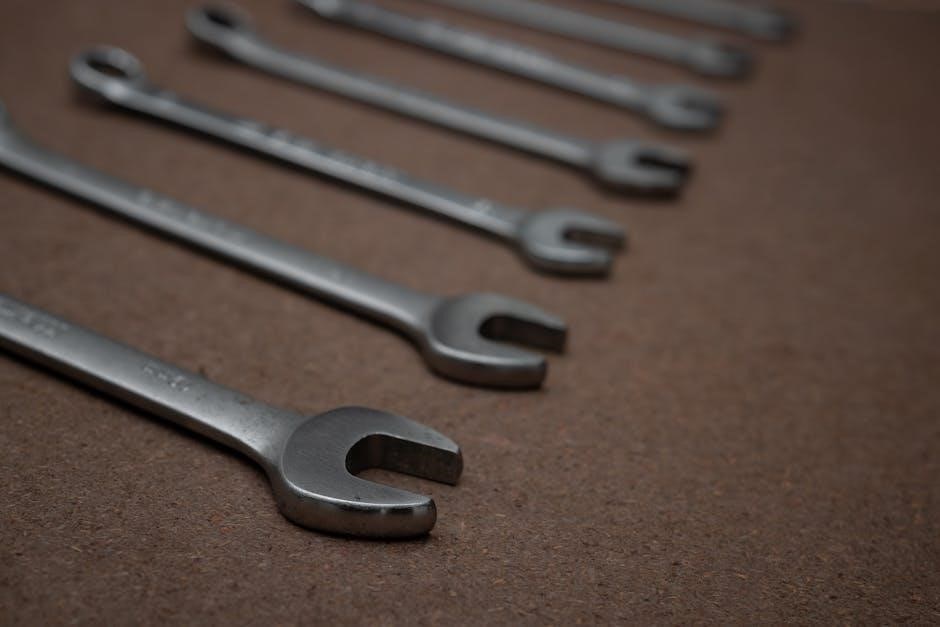
2.2 Technical Specifications and Capabilities

The Miller Syncrowave 250 DX operates on dual voltage (208V and 230/460V) and is designed for both CE and non-CE models. It supports TIG (GTAW) and Stick (SMAW) welding processes with a power range of 3-310 amps for TIG and 3-250 amps for Stick. The unit features a 60% duty cycle at 250 amps for Stick welding and 40% duty cycle at 200 amps for TIG welding. Its compact design measures 24.5 x 14.5 x 28 inches and weighs approximately 281 lbs without the cooler, making it suitable for industrial and professional use.

Installation and Setup

Position the Miller Syncrowave 250 DX on a level, well-ventilated surface. Connect to a suitable power source, ensuring proper grounding. Follow manual instructions carefully.

3.1 Step-by-Step Installation Guide

  1. Place the Miller Syncrowave 250 DX on a level, stable surface in a well-ventilated area.
  2. Connect the unit to a suitable power source, ensuring correct voltage and phase requirements are met.
  3. Install optional running gear or cooler if required, following the manual’s specific instructions.
  4. Ensure proper grounding to prevent electrical hazards and maintain safety.
  5. Connect weld cables securely, keeping them organized to avoid interference.
  6. Test the system at low power to verify proper operation before full use.
  7. Refer to the manual for detailed diagrams and troubleshooting tips if needed.

3.2 Recommended Location and Environment

Place the Miller Syncrowave 250 DX in a well-ventilated, dry area away from flammable materials and direct sunlight. Ensure the unit is on a level, stable surface to prevent vibration. Keep the surrounding environment clean and free from dust to maintain proper cooling. Avoid exposing the unit to extreme temperatures or moisture. Locate the system at least 100 meters away from sensitive electronic equipment to minimize interference. Follow these guidelines to ensure optimal performance and longevity of the welding system.

Operational Modes

The Miller Syncrowave 250 DX supports TIG (GTAW) and Stick (SMAW) welding modes, offering flexibility for various welding tasks. Customizable settings ensure precise control and optimal arc performance.

4.1 TIG (GTAW) Welding Mode

The Miller Syncrowave 250 DX excels in TIG (GTAW) welding mode, offering precise control for clean, high-quality welds. Ideal for thin materials and intricate joints, it features adjustable settings for optimal arc performance. Use the TIG torch with appropriate shielding gas to ensure weld purity. Always clean the workpiece and select the correct tungsten electrode for consistent results. Refer to the manual for specific setup instructions and parameter adjustments to maximize the TIG welding experience.

4.2 Stick (SMAW) Welding Mode

The Miller Syncrowave 250 DX supports Stick (SMAW) welding mode, offering versatility for various electrode types and materials. It provides consistent arc performance and easy ignition. Adjust the amperage control to suit the electrode size and material thickness. Ensure the workpiece is clean and properly grounded for optimal results. Use recommended electrodes and maintain proper electrode condition to achieve strong, durable welds. Refer to the manual for specific settings and techniques to enhance weld quality and penetration in Stick welding applications.

Troubleshooting and Maintenance

Regularly inspect and maintain the Miller Syncrowave 250 DX to ensure optimal performance. Address issues promptly to prevent downtime and maintain welding efficiency and reliability.

5.1 Common Issues and Solutions

Common issues with the Miller Syncrowave 250 DX include power fluctuations, faulty torch connections, and overheating. To resolve these, ensure proper grounding, check for loose connections, and maintain adequate ventilation. For persistent problems, consult the troubleshooting guide or contact Miller technical support. Regular maintenance, such as cleaning the unit and checking coolant levels, can prevent many issues. Always refer to the Miller Syncrowave 250 DX manual for detailed solutions and safety guidelines to maintain optimal performance and extend equipment lifespan.

5.2 Regular Maintenance Tips

Regular maintenance is crucial for the Miller Syncrowave 250 DX. Clean the unit periodically to remove dust and debris, ensuring proper airflow. Check coolant levels and top off as needed. Inspect weld cables for damage or wear and replace them if necessary. Regularly maintain the TIG torch, ensuring the shield cup and tungsten electrode are in good condition. Always follow the Miller Syncrowave 250 DX manual for specific maintenance procedures to prevent downtime and ensure optimal performance. Timely replacements of worn parts will extend the equipment’s lifespan.

Accessories and Optional Equipment

The Miller Syncrowave 250 DX offers compatible running gear and coolers for enhanced portability and cooling efficiency. Additional accessories like TIG torches and stick electrodes are available.

6.1 Compatible Running Gear and Cooler

The Miller Syncrowave 250 DX can be equipped with optional running gear and a cooler for improved portability and thermal management. The running gear provides durable wheels and a robust frame, making it easy to transport the unit to different job sites. The cooler is designed to maintain optimal operating temperatures, ensuring consistent performance during extended welding sessions. These accessories are specifically engineered to enhance the versatility and reliability of the welder, making it suitable for demanding industrial environments. Always ensure compatibility with your unit for optimal functionality.

6.2 Additional Accessories for Enhanced Functionality

Enhance your Miller Syncrowave 250 DX experience with additional accessories designed for optimal performance. Welding torches and remote controls provide precise control and convenience. Consumables, such as tungsten electrodes and collets, ensure clean and consistent welds. Shielding gas kits and flowmeters maintain the perfect atmosphere for TIG and Stick welding. Optional cables and adapters expand connectivity options, while storage cases protect your equipment during transport. These accessories are engineered to maximize the welder’s capabilities and adapt to various welding applications, ensuring a professional-grade result in every project.

Technical Support and Resources

For assistance with the Miller Syncrowave 250 DX, contact Miller Electric Mfg. Co. or visit their website for manuals, troubleshooting guides, and customer support resources.

7.1 Contacting Miller Electric Mfg. Co.

For technical support or inquiries about the Miller Syncrowave 250 DX, contact Miller Electric Mfg. Co. at 1635 W. Spencer Street, Appleton, WI 54914, USA. Call their customer service or visit www.MillerWelds.com for assistance. They provide resources, manuals, and troubleshooting guides to help resolve issues. Ensure to reach out for genuine parts or service to maintain warranty and performance. Their team is available to address concerns and offer expert advice on welding equipment and operations.

7.2 Accessing Additional Manuals and Guides

Additional manuals and guides for the Miller Syncrowave 250 DX are available for free PDF download. These include the Owners Manual (82 pages) and User Manual, covering CE and Non-CE models. Visit www.MillerWelds.com to access these resources; For detailed service and parts information, refer to the Technical Manual, available through your local distributor. Spot welding adjustments and troubleshooting tips are also provided in specific sections of the manual, ensuring comprehensive support for optimal equipment performance and maintenance.

cub cadet st 100 manual

Importance of the Cub Cadet ST 100 Manual

The Cub Cadet ST 100 manual is essential for safe operation, troubleshooting, and maintenance․ It provides detailed instructions to ensure optimal performance and prevent injuries or damage․

1․1․ Safety Precautions and Guidelines

The Cub Cadet ST 100 manual emphasizes critical safety precautions to ensure operator well-being․ It warns against hot engine parts, such as the muffler, which can cause burns․ Users are advised to allow the engine and muffler to cool before touching them․ The manual also restricts operation to individuals who have read and understood the safety rules and instructions․ Failure to comply may result in personal injury․ Additionally, it highlights the importance of following all safety guidelines to prevent accidents and maintain safe operating conditions․ These precautions are vital for the safe and effective use of the Cub Cadet ST 100․

1․2․ Comprehensive Guide for Operation and Maintenance

The Cub Cadet ST 100 manual serves as a detailed guide for operating and maintaining the equipment․ It covers setup, operation, maintenance, and troubleshooting, ensuring users can handle the machine efficiently․ The manual provides step-by-step instructions for routine tasks, such as engine start-up and cutting adjustments․ Additionally, it offers expert tips for optimizing performance and addressing common issues․ By following the manual, users can extend the lifespan of their Cub Cadet ST 100 and ensure it operates at its best․ This comprehensive guide is a valuable resource for both new and experienced operators, making it indispensable for proper equipment care and functionality․

Manual Structure and Content

The Cub Cadet ST 100 manual is organized into clear sections: Set-Up, Operation, Maintenance, Troubleshooting, and Warranty․ It includes detailed engine specifications and key features for optimal use․

2․1․ Sections Included: Set-Up, Operation, Maintenance, Troubleshooting

The manual is divided into four main sections: Set-Up, Operation, Maintenance, and Troubleshooting; The Set-Up section guides users through initial assembly and configuration․ Operation details proper usage techniques and safety measures․ Maintenance provides schedules and tips for keeping the equipment in top condition; Troubleshooting offers solutions for common issues, helping users identify and resolve problems efficiently․ Each section is designed to ensure the Cub Cadet ST 100 performs optimally, with clear instructions and practical advice․

2․2․ Detailed Engine Specifications and Features

The manual provides in-depth details about the Cub Cadet ST 100’s engine, including its 159cc OHV (Overhead Valve) design with AutoChoke technology․ This engine offers efficient power delivery and reduced emissions․ The AutoChoke feature simplifies startup by automatically adjusting the choke․ The manual highlights the engine’s thermal cooling system and durable construction, ensuring longevity and reliable performance․ Additionally, it outlines the 22-inch cutting width and solid 14-inch rear wheels, which enhance stability and maneuverability․ These specifications and features ensure the Cub Cadet ST 100 delivers consistent results for challenging yard tasks․

Obtaining the Cub Cadet ST 100 Manual

The Cub Cadet ST 100 manual is available as a free PDF download online․ Visit the official Cub Cadet website, enter your model number (25A-262J756), and follow the download instructions․

3․1․ Availability of PDF Download Online

The Cub Cadet ST 100 manual is readily available for free download in PDF format․ Users can access it directly from the official Cub Cadet website or authorized platforms․ To download, simply visit the site, locate the “Operators Manuals” section, and enter the model number (e․g․, 25A-262J756) or serial number for an exact match․ The PDF file can be opened using Adobe Acrobat or other PDF readers, ensuring easy access to setup, operation, and maintenance guidelines․ This convenient option allows users to reference the manual anytime, making it an invaluable resource for troubleshooting and ensuring proper equipment care․

3․2․ Requirements for Model and Serial Number

To download the correct Cub Cadet ST 100 manual, users must provide the model number (e․g․, 25A-262J756) and serial number․ These details ensure the manual matches the specific equipment․ The model number can usually be found on the product’s label or in the original packaging․ If the serial number is missing or partially worn off, the model number alone can still provide general guidance․ However, for precise instructions, both numbers are recommended to avoid incorrect information or compatibility issues․ This requirement ensures users receive accurate setup, operation, and maintenance details for their exact unit․

Safety PracticesOutlined in the Manual

The manual emphasizes reading all safety rules before operation․ It includes warnings about hot engine parts and mufflers, stressing the importance of cooling before handling them․

4․1․ General Safety Warnings for Operators

The Cub Cadet ST 100 manual provides critical safety warnings to ensure operator well-being․ Key points include restricting use to individuals who fully understand the manual and following all safety guidelines․ Operators are advised to avoid dangerous practices such as operating the machine near open flames or sparks, which could ignite fuel vapors․ Additionally, the manual emphasizes the importance of proper attire, including protective eyewear and sturdy footwear, to minimize injury risks․ It also cautions against operating the machine when fatigued or under the influence of substances that impair judgment․ By adhering to these warnings, users can significantly reduce the likelihood of accidents and ensure a safe operating environment․

4․2․ Precautions for Engine and Muffler Safety

The manual highlights vital safety measures for the engine and muffler․ Operators are warned that these components become extremely hot during operation and can cause severe burns if touched․ It is crucial to allow the engine and muffler to cool down completely before performing any maintenance or inspections․ Additionally, the manual advises against modifying the muffler or exhaust system, as this could lead to carbon monoxide risks or other hazards․ Proper handling and regular checks are emphasized to prevent overheating and ensure the longevity of the engine and muffler․ Adhering to these precautions is essential for safe and efficient machine operation․

Features and Specifications of the Cub Cadet ST 100

The Cub Cadet ST 100 features a powerful 159cc OHV engine, 22-inch cutting width, and durable design for efficient yard tasks․ Its AutoChoke system ensures easy starts, while high rear wheels enhance mobility and control, making it ideal for trimming and mowing․

5․1․ 159cc OHV Engine with AutoChoke

The Cub Cadet ST 100 is equipped with a 159cc OHV engine, delivering robust power for efficient cutting․ The AutoChoke feature simplifies starting, eliminating the need for manual priming․ This engine design ensures consistent performance, handles tough grass, and provides reliable operation․ Its overhead valve technology enhances fuel efficiency and reduces emissions, making it environmentally friendly․ The engine’s thermal AutoChoke ensures smooth startups in various conditions, while its vertical shaft design optimizes power delivery to the cutting system․ This combination of power and convenience makes the ST 100 ideal for demanding yard tasks, ensuring durability and ease of use for operators․

5․2․ 22-Inch Cutting Width and Durable Design

The Cub Cadet ST 100 features a 22-inch cutting width, enabling efficient coverage of larger areas with fewer passes․ Its durable design includes a robust steel deck and high-quality components, ensuring long-lasting performance․ The unit is built to withstand tough yard conditions, with a focus on reliability and ease of use․ The 14-inch high rear wheels with ball bearings enhance maneuverability, making it easier to navigate uneven terrain․ Additionally, the unique deck shape allows for precise trimming against fences and walls, while the heavy-duty cutting line ensures consistent results․ This combination of width and durability makes the ST 100 a versatile tool for maintaining various yard sizes․

Troubleshooting Common Issues

The Cub Cadet ST 100 manual helps identify and resolve common issues like engine performance problems or cutting inefficiency, ensuring quick fixes for optimal functionality․

6․1․ Engine Performance Problems

The Cub Cadet ST 100 manual addresses common engine issues such as poor starting, rough running, or loss of power․ It provides diagnostic steps to identify problems like faulty spark plugs, clogged air filters, or improper fuel use․ Troubleshooting guides help users resolve issues efficiently, ensuring the 159cc OHV engine operates smoothly․ Regular maintenance, such as checking oil levels and cleaning filters, is emphasized to prevent engine performance degradation․ By following the manual’s instructions, users can restore their engine’s optimal functionality and extend its lifespan․ This section is crucial for maintaining the machine’s reliability and performance․

6․2․ Cutting and Trimming Efficiency

The Cub Cadet ST 100 manual offers tips to maximize cutting and trimming efficiency․ Its 22-inch cutting width and heavy-duty, square ․155 lines ensure quick and precise results․ Proper blade maintenance, such as sharpening and cleaning, is emphasized to maintain sharp cuts․ Regular checks on the cutting line length and deck alignment are recommended to avoid uneven trimming․ Additionally, the manual advises on optimal mowing techniques, like mowing in a pattern and not cutting too much grass at once․ By following these guidelines, users can achieve consistent and efficient cutting performance while extending the machine’s lifespan․

Maintenance and Service Guidelines

Regular maintenance ensures optimal performance and longevity of the Cub Cadet ST 100․ The manual outlines tasks like oil changes, blade sharpening, and part replacements for consistent results․

7․1․ Regular Maintenance Schedule

The Cub Cadet ST 100 manual provides a detailed maintenance schedule to ensure optimal performance․ Regular tasks include oil changes, blade sharpening, and air filter cleaning․ It also recommends inspecting and replacing the spark plug annually․ Proper lubrication of moving parts and checking tire pressure are emphasized to maintain efficiency․ The schedule outlines specific intervals for each task, ensuring the mower remains reliable and efficient․ Adhering to this routine helps prevent breakdowns and extends the product’s lifespan․ Always refer to the manual for exact timing and procedures to keep your Cub Cadet ST 100 in top condition․

7․2․ Replacement Parts and Accessories

The Cub Cadet ST 100 manual highlights the importance of using genuine replacement parts and accessories to maintain performance and safety․ It lists essential components like blades, air filters, spark plugs, and belts, providing part numbers for easy identification․ Users are advised to purchase these items from authorized dealers or Cub Cadet’s official website to ensure compatibility and warranty validity․ The manual also offers guidance on installing these parts correctly, emphasizing the need to follow instructions to avoid damage or injury․ Regularly updating with authentic accessories ensures the mower operates efficiently and reliably over time․

Warranty Information

The Cub Cadet ST 100 manual outlines the warranty period and coverage, ensuring protection for defective parts․ It requires the model and serial number for validation and details conditions for warranty eligibility, ensuring compliance with specified terms for repairs and replacements․

8․1․ Warranty Period and Coverage

The Cub Cadet ST 100 warranty period begins on the original purchase date or delivery date, whichever is later․ It covers defective parts and ensures repairs or replacements under specified conditions․ The warranty disclaimer outlines that engine horsepower is for comparison purposes only, and pricing may vary by location․ Warranty details are available through local dealers, and conditions require adherence to manual instructions․ The warranty ensures protection for owners, covering manufacturing defects and promoting reliable performance․ Proper registration and maintenance are essential for warranty validity, as outlined in the manual․

8․2․ Conditions for Warranty Validity

The Cub Cadet ST 100 warranty remains valid under specific conditions․ Proper registration and adherence to the maintenance schedule are essential․ The product must be used as intended, and only genuine parts should be installed․ Failure to follow the manual’s instructions may void the warranty․ The warranty covers manufacturing defects but excludes damage caused by misuse or neglect․ Proof of purchase is required for warranty claims․ Regular maintenance, as outlined in the manual, ensures warranty coverage remains effective․ Compliance with all specified conditions guarantees optimal protection and performance of the Cub Cadet ST 100․

dbxr463ed1ww repair manual

This manual provides essential guidance for maintaining and repairing the GE DBXR463ED1WW dryer‚ ensuring optimal performance and longevity. It covers key components‚ troubleshooting‚ and DIY repair solutions.

Overview of the GE DBXR463ED1WW Dryer Model

The GE DBXR463ED1WW is a reliable electric dryer designed for efficient drying performance. It features a spacious 6.0 cu. ft. capacity‚ ideal for handling large laundry loads. Known for its durability‚ this model includes components like the rear drum bearing and a robust exhaust system. The dryer is built with user-friendly controls and multiple cycle options‚ ensuring versatile operation. Its design emphasizes energy efficiency and consistent drying results. This model is a popular choice for homeowners seeking a dependable appliance. The manual provides detailed insights into its construction and operation‚ aiding in troubleshooting andmaintenance.

Importance of Regular Maintenance and Repair

Regular maintenance and repair are crucial for ensuring the GE DBXR463ED1WW dryer operates efficiently and safely; By addressing issues early‚ you can prevent unexpected breakdowns and extend the appliance’s lifespan. Simple tasks like cleaning the lint filter and checking the exhaust system can significantly improve performance and reduce energy consumption. The repair manual offers cost-effective solutions‚ guiding you through necessary upkeep and minor fixes. Consistent care not only enhances reliability but also helps maintain optimal drying results. Stay proactive with routine inspections to keep your dryer in top condition.

Key Components of the GE DBXR463ED1WW Dryer

The GE DBXR463ED1WW dryer features essential components like the dryer drum‚ bearings‚ exhaust duct‚ heating element‚ and thermal sensors‚ all crucial for efficient and safe operation.

Dryer Drum and Bearing Assembly

The dryer drum and bearing assembly are vital for smooth operation. The drum rotates clothes during cycles‚ while bearings reduce friction and noise. Over time‚ bearings may wear out‚ causing noise or vibration. Regular inspection is crucial to prevent damage. Replacing worn bearings ensures quiet operation and extends the dryer’s lifespan. Proper installation of the bearing kit‚ including the shaft and ground strap‚ is essential for optimal performance. Ensure all parts are securely fastened to maintain drum stability and functionality.

Exhaust Duct and Venting System

The exhaust duct and venting system are critical for safely removing moisture and lint from the dryer. A clogged or damaged duct can lead to inefficiency‚ higher energy bills‚ or even fire hazards. Regular cleaning of the duct and vent ensures proper airflow and prevents lint buildup. Inspect for kinks‚ dents‚ or blockages and replace any damaged sections. Use OEM parts for compatibility and reliability. Proper installation and maintenance of the venting system are essential for optimal dryer performance and safety. Always follow the manufacturer’s guidelines for venting configurations and cleaning schedules.

Heating Element and Thermal Sensors

The heating element in the GE DBXR463ED1WW dryer generates heat during the drying cycle‚ while thermal sensors monitor and regulate temperature to prevent overheating. These sensors ensure safe operation by detecting abnormal heat levels and shutting off the dryer if necessary. Regular inspection of the heating element for damage or wear is essential‚ as a faulty element can lead to poor drying performance or complete failure. Cleaning the sensors and ensuring proper airflow also help maintain accurate temperature control. Replacing these components requires careful adherence to the manual’s instructions to avoid further damage or safety risks.

Recommended Maintenance Tips

Regular maintenance ensures optimal performance. Clean the exhaust duct and check for blockages to improve efficiency and safety. Inspect and replace worn parts as needed.

Cleaning the Lint Filter and Exhaust Duct

Cleaning the lint filter after every use is essential to maintain efficiency and safety. Remove and wash the filter with water to eliminate any buildup. For the exhaust duct‚ use a brush or vacuum to clear lint and debris. Regularly inspect the duct for blockages‚ as clogged vents can cause poor performance and potential fire hazards. Ensure all connections are secure and replace damaged sections if necessary. This simple maintenance step will improve airflow‚ reduce drying times‚ and prevent overheating issues. Always refer to your manual for specific instructions on accessing and cleaning these components safely and effectively.

Inspecting and Replacing the Rear Drum Bearing

Regular inspection of the rear drum bearing is crucial to ensure smooth operation and prevent damage. Use a screwdriver to access the bearing by removing the back panel. Look for signs of wear‚ such as excessive noise or visible damage. If damaged‚ replace the bearing kit‚ which typically includes a shaft‚ ground strap‚ and screws. Refer to the manual or a diagram for precise instructions. Always unplug the dryer before starting any repair to ensure safety. Replacing the bearing promptly can prevent further issues and extend the dryer’s lifespan.

Keeping the Exterior Clean and Functional

Regularly cleaning the exterior of your GE DBXR463ED1WW dryer is essential for maintaining its appearance and functionality. Use a soft cloth and mild detergent to wipe down the surface‚ removing dust and lint buildup. Ensure all buttons and controls are free from debris for proper operation. Check the exterior vents for blockages‚ as restricted airflow can hinder performance. Avoid using harsh chemicals or abrasive cleaners‚ as they may damage the finish. Keeping the exterior clean not only enhances its aesthetic appeal but also helps prevent potential issues related to overheating or malfunctioning components.

Common Repair Issues and Solutions

Noisy operation often stems from worn drum bearings or misaligned parts. Overheating issues may arise from clogged vents or faulty thermal sensors. Addressing these promptly ensures efficient performance and prevents further damage.

Troubleshooting Noisy Operation

Noisy operation in the GE DBXR463ED1WW dryer is often caused by worn drum bearings‚ misaligned drum support brackets‚ or a loose drum belt. Start by inspecting the rear drum bearing assembly for excessive wear or damage. If the bearing or bracket is damaged‚ replacing them with an OEM rear drum bearing kit is recommended. Additionally‚ check the drum belt for proper tension and alignment. If the belt is loose or frayed‚ replace it to ensure smooth operation. Always unplug the dryer before attempting any repairs to ensure safety.

Fixing the Rear Bearing Bracket and O-Ring

Fixing the rear bearing bracket and O-ring on your GE DBXR463ED1WW dryer involves replacing worn or damaged parts. Start by accessing the rear drum bearing assembly‚ ensuring the dryer is unplugged. Inspect the bracket for wear and the O-ring for cracks or deformation. Replace the rear drum bearing kit‚ which includes the bracket‚ O-ring‚ and screws. Properly align and secure the new parts to prevent noise and ensure smooth drum rotation. Follow the installation instructions provided with the kit for precise fitting. This repair is manageable with basic tools but may require patience and attention to detail.

Replacing the Drum Bearing Kit

Replacing the drum bearing kit in your GE DBXR463ED1WW dryer is essential for addressing noisy operation and ensuring smooth drum rotation. Begin by disconnecting power and accessing the internal components. Remove the drum to inspect the bearing assembly for wear or damage. Replace the entire kit‚ which typically includes a shaft‚ ground strap‚ bearing‚ and screws. Align the new bearing plate securely and reattach the drum. Ensure all parts are tightly fastened to prevent vibration. Follow the installation instructions provided with the kit for accurate fitting. This repair restores the dryer’s efficiency and reduces operational noise effectively.

Step-by-Step Repair Instructions

This section provides detailed‚ easy-to-follow instructions for safely repairing your GE DBXR463ED1WW dryer‚ including disassembling‚ replacing parts‚ and reconnecting components to ensure proper function and safety.

Accessing the Internal Components Safely

To safely access internal components of your GE DBXR463ED1WW dryer‚ unplug the power cord and allow the dryer to cool. Remove the lint filter and vents for clearance. Use a screwdriver to take out screws securing the top panel and back panel. Gently pry open the panels‚ taking care not to damage wiring or connections. Disconnect electrical connectors and ground straps before accessing the drum or heating elements. Always follow safety guidelines to avoid injuries or further damage during disassembly. Ensure the dryer is stable and secure during repair to prevent accidents.

Installing Replacement Parts

When installing replacement parts in your GE DBXR463ED1WW dryer‚ ensure proper alignment and secure fastening. For the rear drum bearing‚ align the bracket with the shaft and tighten screws evenly. Replace the o-ring if damaged to maintain a proper seal. Heating elements should be connected securely‚ ensuring electrical connections are tight and insulated. After installation‚ test the dryer at a low setting to confirm functionality and safety. Always refer to the manual for specific torque specifications and wiring diagrams to avoid errors. Proper installation ensures optimal performance and prevents future issues.

Reassembling the Dryer After Repair

Reassembling the GE DBXR463ED1WW dryer requires careful attention to detail. Start by aligning the rear drum bearing with the shaft and securing it with screws. Reattach the drum belt‚ ensuring it is tightly fastened to the motor pulley. Reconnect the exhaust duct and venting system‚ making sure all connections are airtight. Replace the top and side panels‚ tightening screws firmly. Finally‚ plug in the dryer and run a test cycle to ensure everything operates smoothly. Proper reassembly is crucial for safe and efficient performance. Always refer to the manual for specific alignment and torque requirements.

Resources for DIY Repair

Access official GE manuals‚ diagrams‚ and repair videos. Find genuine parts and tools online. Utilize expert advice and detailed step-by-step instructions for a smooth repair process.

Official GE Manuals and Diagrams

GE provides comprehensive manuals and detailed diagrams for the DBXR463ED1WW dryer‚ ensuring accurate repairs. These resources include exploded views of components‚ electrical schematics‚ and part numbers. They guide users through disassembly‚ troubleshooting‚ and reassembly. Official manuals are available for download‚ offering step-by-step instructions and error code tables. Diagrams help identify parts like the rear drum bearing and heating element. Access these resources to ensure your repairs are precise and effective‚ maintaining your dryer’s performance and safety. Use these tools to diagnose and fix issues confidently.

Online Videos and Expert Repair Help

Online videos and expert repair resources offer detailed guidance for fixing the GE DBXR463ED1WW dryer. Platforms provide step-by-step tutorials‚ covering common repairs like replacing the rear drum bearing or fixing noisy operation. These videos often include close-up shots and clear instructions‚ making complex tasks easier to understand. Additionally‚ expert forums and repair communities share tips and solutions based on real experiences. With visual and written guidance‚ users can confidently address issues‚ ensuring repairs are done safely and effectively. These resources are invaluable for DIY enthusiasts seeking to resolve problems without professional assistance.

OEM Parts and Tools

Using OEM parts ensures compatibility and longevity for your GE DBXR463ED1WW dryer. Genuine components‚ such as the rear drum bearing kit‚ heating elements‚ and O-rings‚ are designed to meet exact specifications. These parts are readily available from official GE sources or authorized retailers. Detailed diagrams and installation instructions often accompany OEM kits‚ making repairs more straightforward. Investing in authentic tools and parts guarantees safe and efficient fixes‚ maintaining your dryer’s performance and warranty compliance. Always verify the authenticity of parts to avoid inferior substitutes that may compromise functionality or safety.

flex ex2 manual

Welcome to the Flex EX2 Manual, your comprehensive guide to understanding and utilizing the Flex EX2 system effectively. This manual provides essential information on safety, installation, operation, and troubleshooting to ensure optimal performance and longevity of your device. Refer to the official Magnetek documentation for detailed instructions and support.

1.1 Overview of the Flex EX2 System

The Flex EX2 System is a advanced wireless control solution designed for industrial applications, offering enhanced performance and durability compared to its predecessor, the Flex EX. It consists of a transmitter handset and receiver unit, with standard accessories like a waist belt and spare parts. The system is known for its rugged design and improved wireless control capabilities, making it a reliable choice for demanding environments. This manual provides a detailed overview of its components, features, and operation.

1.2 Importance of the Manual for Users

This manual is essential for users to safely and effectively operate the Flex EX2 System. It provides detailed instructions for installation, operation, and maintenance, ensuring optimal performance and longevity. The guide also includes troubleshooting tips and compliance information, helping users avoid potential issues and adhere to regulatory standards. Referencing this manual is crucial for understanding system capabilities and proper usage.

Key Features of the Flex EX2

The Flex EX2 offers enhanced performance, durability, and advanced wireless control capabilities. It includes improved signal strength, customizable settings, and compatibility with optional accessories for expanded functionality.

2;1 Enhanced Performance and Durability

The Flex EX2 boasts enhanced performance with improved signal strength and reliability. Its durable design ensures longevity, even in challenging environments. Advanced engineering provides better resistance to wear and tear, making it a robust choice for demanding applications. The system’s rugged construction and high-quality materials contribute to its superior durability compared to previous models.

2.2 Improved Wireless Control Capabilities

The Flex EX2 features enhanced wireless control capabilities, offering improved signal strength and range. Its advanced radio frequency technology ensures reliable communication between the transmitter and receiver. The system supports seamless operation in challenging environments, reducing interference and ensuring consistent performance. These upgrades make the Flex EX2 more versatile and user-friendly compared to its predecessor, the Flex EX.

Flex EX2 System Components

The Flex EX2 system includes a transmitter handset, receiver unit, and standard accessories like a waist belt and spare battery, ensuring reliable wireless control operation.

3.1 Transmitter Handset and Receiver Unit

The Flex EX2 system features a transmitter handset and receiver unit, designed for seamless wireless control. The transmitter includes an intuitive interface with channel selection and a clear display, while the receiver connects to your equipment securely. Pairing is straightforward, ensuring a reliable connection. Both units are built with durable materials for long-lasting performance and durability in various environments.

3.2 Standard and Optional Accessories

The Flex EX2 system includes standard accessories like a transmitter waist belt and spare battery for convenience. Optional enhancements such as extended antennas improve signal strength, while heavy-duty cases provide added protection; Additional accessories, including premium chargers and mounting brackets, are available to customize your setup for specific applications, ensuring versatility and reliability in various operational environments.

Installation and Setup

The Flex EX2 installation involves proper antenna placement and I-Chip setup to ensure optimal performance and signal strength, crucial for reliable operation.

4.1 Step-by-Step Installation Guide

The Flex EX2 manual provides a detailed step-by-step installation guide to ensure optimal performance. Begin by mounting the receiver unit securely and positioning the antenna for maximum signal strength. Next, install the I-Chip in the transmitter handset, ensuring it’s properly aligned and seated. Connect all necessary components, then pair the transmitter and receiver according to the manual’s instructions. Finally, test the system to confirm proper operation and adjust the antenna if needed. Always refer to the official manual for specific guidance.

4.2 I-Chip Installation in the Transmitter

Installing the I-Chip in the Flex EX2 transmitter is a critical step for system functionality. Ensure the transmitter is powered off before starting. Open the transmitter housing and locate the I-Chip slot. Carefully align the I-Chip with the slot, ensuring it is properly seated. Secure the chip firmly to avoid any loose connections. Close the housing and power on the transmitter to test the system. Refer to the manual for detailed visuals and alignment instructions.

Operating the Flex EX2

Mastering the Flex EX2 operation involves understanding its basic functions and advanced customization options. This section guides you through seamless control, ensuring efficient and precise system management.

5.1 Basic Operation and Functions

The Flex EX2 system operates through a transmitter handset and receiver unit, enabling seamless wireless control. Basic functions include channel selection, volume adjustment, and signal transmission. The transmitter features an intuitive interface for easy navigation. Ensure proper pairing by following the FLEX Pairing Guide. Standard accessories like the waist belt enhance portability. Regularly check antenna alignment for optimal signal strength. Refer to the manual for detailed operational procedures and troubleshooting tips.

5.2 Advanced Features and Customization

The Flex EX2 offers advanced features such as programmable buttons and customizable profiles, allowing users to tailor the system to their specific needs. Firmware updates enhance functionality, while the intuitive interface supports personalized settings. Users can adjust sensitivity, response time, and transmission modes for precise control. Refer to the manual for detailed guidance on configuring these features to maximize efficiency and performance. Regular updates ensure optimal system operation.

Safety Information and Precautions

Always follow Flex EX2 safety guidelines to avoid accidents. Ensure proper handling, avoid extreme temperatures, and keep the system away from water. Compliance with regulatory standards is essential for safe operation and longevity of the device. Refer to the official Magnetek documentation for detailed safety protocols and precautions to ensure optimal performance and user safety. Proper usage enhances durability and reliability.

6.1 General Safety Guidelines

Adhere to general safety guidelines when using the Flex EX2 system. Avoid exposing the device to extreme temperatures, moisture, or physical stress. Ensure proper handling to prevent damage. Keep the system away from water and corrosive substances. Follow all warnings and precautions outlined in the official Magnetek documentation. Proper usage and adherence to guidelines ensure optimal performance, longevity, and user safety. Always prioritize safety to maintain device reliability and functionality.

6.2 Compliance with Regulatory Standards

The Flex EX2 system complies with all applicable regulatory standards, ensuring safe and reliable operation. It meets FCC guidelines and CE standards, guaranteeing conformity with international safety and performance requirements. Compliance with these standards ensures the device operates within legal frameworks, minimizing interference with other electronic systems. Always verify that your system adheres to local regulations for uninterrupted and lawful use. Compliance is crucial for maintaining operational integrity and avoiding potential legal issues.

Troubleshooting Common Issues

Troubleshooting the Flex EX2 involves identifying and resolving issues like signal loss or interference. Refer to the manual for step-by-step solutions to ensure smooth operation and optimal performance.

7.1 Identifying and Resolving Common Problems

Identifying and resolving common issues with the Flex EX2 system is crucial for maintaining optimal performance. Common problems include signal interference, connectivity issues, or antenna misalignment. To resolve these, ensure proper antenna installation, check for physical obstructions, and verify wireless channel settings. Refer to the troubleshooting guide in the manual for detailed solutions. Regularly updating software and resetting the system can also address many issues effectively.

7.2 Antenna Installation and Signal Strength

Proper antenna installation is crucial for maximizing signal strength in the Flex EX2 system. Ensure antennas are installed away from metal structures and aligned correctly to avoid interference. Mount antennas at least 10 feet above ground for optimal coverage. Regularly check the signal strength LED on the receiver and refer to the installation guide for troubleshooting weak signals or connectivity issues.

Maintenance and Care

Regular maintenance ensures the Flex EX2 system operates efficiently. Clean surfaces, inspect connections, and check battery levels. Update software and firmware as recommended for optimal performance.

8.1 Routine Maintenance Tips

Regularly clean the Flex EX2 transmitter and receiver to prevent dust buildup. Check battery levels and charge as needed. Inspect antenna connections for tightness and damage. Update software and firmware periodically to ensure optimal functionality. Store the system in a dry, cool environment to prevent moisture damage. Refer to the official Magnetek manual for detailed care instructions.

8.2 Software and Firmware Updates

Regularly updating your Flex EX2 system’s software and firmware ensures optimal performance and security. Download the latest versions from the official Magnetek website or through the provided links in the manual. Follow the step-by-step guide in the Flex EX2 Instruction Manual to install updates correctly. Keep your system up-to-date to access new features and improvements, ensuring enhanced functionality and reliability.

Accessories for Flex EX2

The Flex EX2 system comes with standard accessories like a transmitter waist belt and spare parts. Optional accessories, such as additional antennas, enhance functionality and convenience for users.

9.1 Standard-Equipped Accessories

The Flex EX2 system includes standard accessories such as a transmitter waist belt and spare battery for convenience. These items ensure ease of use and portability, while optional accessories like additional antennas or chargers can further enhance functionality. The system is designed to provide a comprehensive solution, catering to both basic and advanced user needs with its versatile range of included and optional components.

9.2 Optional Accessories for Enhanced Functionality

Optional accessories for the Flex EX2 include advanced antennas for improved signal strength and range, as well as additional chargers and carrying cases. These extras allow users to customize their system to meet specific needs, ensuring enhanced performance and convenience. By incorporating these optional components, users can optimize their experience and maximize the versatility of the Flex EX2 system for diverse applications and environments.

Comparison with Flex EX

Flex EX2 offers enhanced features, improved durability, and better wireless control compared to the original Flex EX. Upgrades include advanced performance and extended functionality.

10.1 Upgrades and Improvements in EX2

The Flex EX2 features several upgrades, including improved wireless control capabilities, enhanced performance, and increased durability compared to the original Flex EX. It offers better signal range, customizable controls, and advanced troubleshooting options. The EX2 also includes enhanced security features and compatibility with a wider range of accessories, making it a more versatile and reliable choice for users.

10.2 Cost-Effectiveness and Value

The Flex EX2 offers exceptional value, combining advanced features with affordability. Its enhanced durability and improved performance reduce long-term maintenance costs. With a wide range of standard and optional accessories, users can customize their system without excessive spending. The EX2 provides a cost-effective solution for those seeking reliability and functionality, making it a practical upgrade from the original Flex EX.

Manuals and Downloads

Access comprehensive Flex EX2 manuals, including pairing guides, instruction manuals, and troubleshooting resources. Download official documentation and support materials for seamless system operation and maintenance.

11.1 Available Manuals and Guides

The Flex EX2 system offers a variety of downloadable resources, including the Flex EX2 Pairing Guide, Flex 4EX2 Manual, Flex 6EX2 Manual, and Flex 12ES/EX2 Instruction Manual. Additional guides cover topics like antenna installation, troubleshooting, and software updates. These resources are designed to provide detailed instructions for installation, operation, and maintenance, ensuring optimal performance of your Flex EX2 system.

11.2 Downloading Software and Documentation

The Flex EX2 system offers downloadable resources, including the Flex EX2 Pairing Guide and Flex 4EX2 Manual. Visit the official Magnetek website to access these documents freely. Ensure your device meets system requirements for smooth installation. Regularly check for software and firmware updates to maintain optimal performance. Downloading from authorized sources ensures compatibility and security for your Flex EX2 system.

Welcome to the conclusion of the Flex EX2 Manual. This guide has covered essential topics, from installation to troubleshooting, ensuring optimal use of your device. Refer to the manual regularly for maintenance tips and updates. For further assistance, consult official Magnetek resources or contact their support team.

12.1 Summary of Key Points

The Flex EX2 Manual provides a detailed guide for installing, operating, and maintaining the system. Key topics include safety precautions, troubleshooting, and routine maintenance. The manual emphasizes the importance of proper installation and adherence to regulatory standards. Regular updates and firmware checks ensure optimal performance. Refer to the manual for comprehensive instructions and utilize official resources for additional support and documentation.

12.2 Final Tips for Optimal Use

For the best experience with your Flex EX2, ensure regular software updates and perform routine maintenance. Always use genuine accessories and follow safety guidelines. Store the system in a dry, cool environment to prevent damage. Familiarize yourself with the manual for advanced features and troubleshooting. Proper antenna alignment and signal checks can enhance performance. Keep the manual handy for quick reference and optimal functionality.

References

Consult the official Flex EX2 documentation and additional resources for comprehensive support. Download manuals, guides, and software updates from authorized sources for enhanced functionality and troubleshooting.

13.1 Official Flex EX2 Documentation

The official Flex EX2 documentation includes comprehensive manuals, installation guides, and technical specifications. These resources are provided by Magnetek to ensure proper installation, operation, and maintenance of the system. The manuals cover safety information, troubleshooting, and advanced features, making them indispensable for users seeking detailed operational guidance and compliance with regulatory standards. Always refer to these documents for accurate and reliable information.
13.2 Additional Resources and Support

Beyond the official manual, users can access downloadable guides, troubleshooting tips, and FAQs from Magnetek’s official website. Additional support includes customer service and technical assistance for addressing specific queries or issues. Optional training materials and user forums also provide valuable insights and community-driven solutions, ensuring comprehensive support for the Flex EX2 system.