This manual provides essential guidance for installing the Aprilaire 400 humidifier, ensuring proper setup and operation. It covers installation steps, safety guidelines, and maintenance tips.
1.1 Overview of the Aprilaire 400 Humidifier
The Aprilaire 400 humidifier is a high-efficiency, whole-house solution designed to maintain optimal humidity levels. It can be installed on either the supply or return plenum of a forced air system, offering flexibility. Compact in size, it operates quietly and efficiently, providing consistent humidity without excessive water usage. The unit is reversible, accommodating right or left-hand bypass connections. Its design ensures minimal water waste and energy consumption, making it an eco-friendly choice for homeowners seeking precise humidity control and improved indoor air quality.
1.2 Importance of Proper Installation
Proper installation of the Aprilaire 400 humidifier is crucial for ensuring optimal performance, safety, and energy efficiency. Incorrect installation can lead to poor humidity control, increased energy bills, and potential damage to the unit or HVAC system. Following the manufacturer’s guidelines ensures the humidifier operates safely and efficiently, maintaining desired humidity levels without excessive water usage. Improper installation may also void the warranty, making it essential to adhere to the provided instructions. Correct setup guarantees reliable operation and extends the lifespan of the humidifier, ensuring it meets your home’s humidity needs effectively.
Pre-Installation Considerations
Before installation, review the manual, ensure compatibility with your HVAC system, and prepare all necessary tools and materials for a smooth setup process.
2.1 Understanding the System Requirements
Understanding the system requirements for the Aprilaire 400 humidifier ensures compatibility with your HVAC setup. The unit can be installed on either the supply or return plenum, offering flexibility. It requires a 24VAC transformer and proper drainage. Ensure your system meets these specifications before proceeding to avoid installation issues. Proper alignment with your HVAC system’s operation is crucial for optimal performance and humidity control.

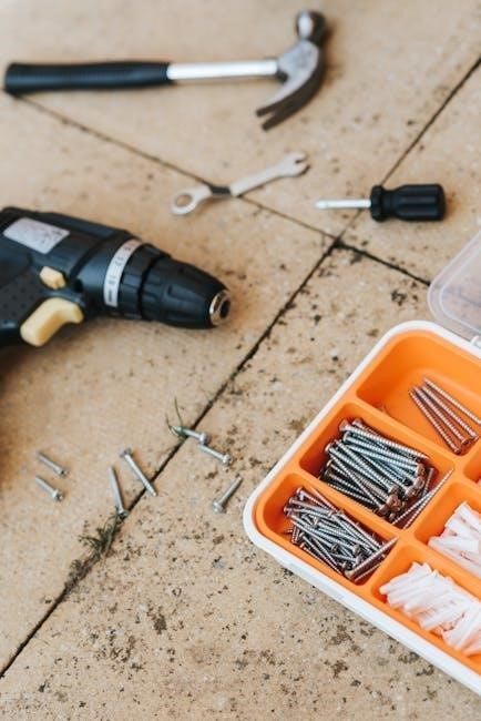
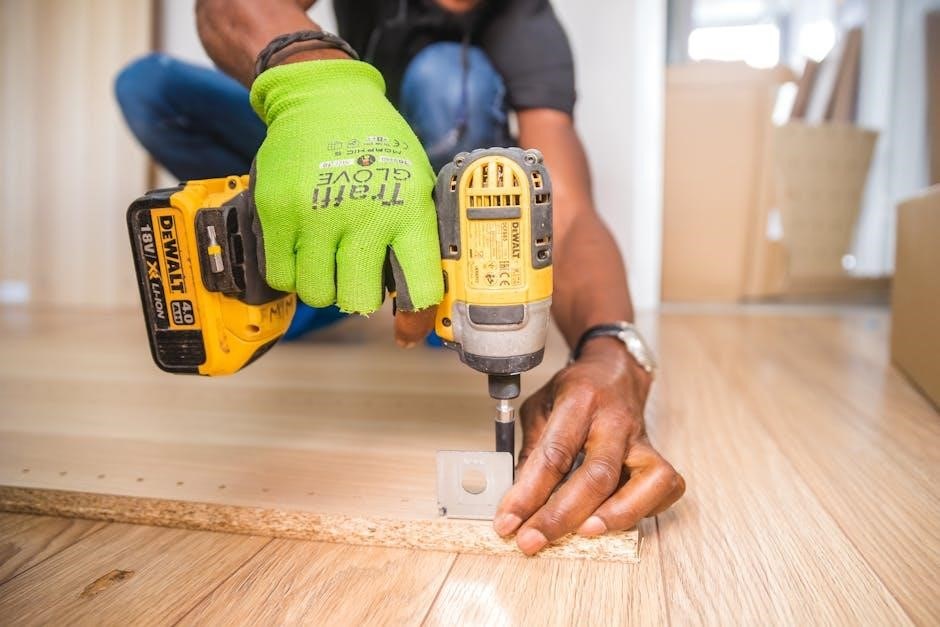
2.2 Gathering Necessary Tools and Materials
To ensure a smooth installation, gather all required tools and materials beforehand. These include a drill, screwdrivers, wrenches, and fasteners. The installation template provided with the humidifier is essential for accurate mounting. Additionally, ensure you have the bypass duct, water panel, and 24VAC transformer. Proper materials like foam tape and insulation may be needed to maintain system efficiency. Having all components ready will prevent delays and ensure the installation process is completed efficiently and correctly.
Key Components of the Aprilaire 400 Humidifier
The Aprilaire 400 includes a humidifier unit, bypass duct, water panel, and control system. These components work together to efficiently humidify your home’s air.
3.1 Humidifier Unit and Accessories
The Aprilaire 400 humidifier unit is designed for efficient operation, featuring a compact design that integrates seamlessly with HVAC systems. The unit measures 15 x 14.375 x 10 inches, making it suitable for various installation scenarios. It includes essential accessories like the bypass duct, water panel, and mounting hardware. The humidifier unit is reversible, allowing for flexible installation on either the supply or return plenum. Accessories such as the water panel ensure optimal moisture evaporation, while the bypass duct facilitates airflow. Proper installation of these components is crucial for maintaining energy efficiency and consistent humidity levels.
3.2 Bypass Duct and Water Panel
The bypass duct is a critical component that directs airflow through the humidifier, ensuring efficient moisture distribution. It is reversible, accommodating both right-hand and left-hand configurations. The water panel, located inside the humidifier, is designed to maximize water evaporation. It captures excess water in a reservoir, enhancing efficiency. Proper alignment and installation of these components are essential for optimal performance. The bypass duct and water panel work together to deliver precise humidity control, ensuring consistent comfort in your home.
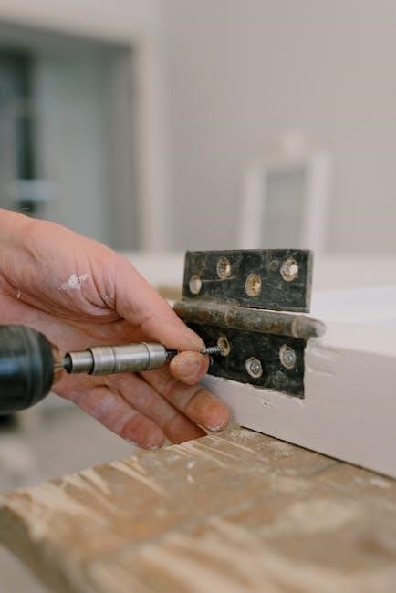
Installation Steps
Follow detailed instructions for preparing the site, mounting the humidifier, connecting the bypass duct, and wiring the control for a successful setup and operation.
4.1 Preparing the Installation Site
Before installation, ensure the site is clean, dry, and accessible. The Aprilaire 400 can be installed on either the supply or return plenum. Measure the space to accommodate the unit’s dimensions (15 x 14.375 x 10 inches). Ensure proximity to a water supply and drainage system. Use the provided installation template to mark the plenum accurately for mounting holes. Verify that the area is free from obstructions and offers adequate clearance for maintenance. Proper preparation ensures a smooth and successful installation process.
4.2 Mounting the Humidifier on the Plenum
Mount the Aprilaire 400 humidifier on the plenum, ensuring it is level and securely fastened. The unit can be installed on either the supply or return plenum and is reversible for right or left-hand bypass connections. Use the provided installation template to mark the mounting holes accurately. Align the humidifier with the marked holes and secure it using the recommended screws. Ensure the bypass duct connection is properly positioned and aligned before tightening. Double-check that the unit is firmly attached to prevent vibration and ensure efficient operation.
4.3 Connecting the Bypass Duct
The bypass duct connects the humidifier to your HVAC system, ensuring proper humidity distribution. Attach one end of the 6-inch insulated duct to the humidifier’s outlet and the other to the plenum. Ensure the duct is securely fastened and sealed to prevent air leaks. If installing on the supply plenum, route the duct to the return side for balanced airflow. Verify alignment and connection tightness to maintain efficient operation and prevent moisture issues. Follow the manufacturer’s guidelines for optimal performance and system integration.
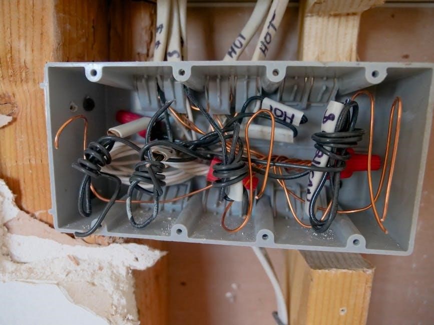
Wiring the Humidifier Control
Connect the 24VAC transformer to a dedicated power source, not shared with the furnace. Wire the humidifier control to the HVAC system, ensuring proper connections for humidity control. Follow the manual for specific wiring instructions to ensure safe and efficient operation.
5.1 Connecting the 24VAC Transformer
Connect the 24VAC transformer to a dedicated 120V power source, ensuring it is not shared with the furnace. Wire the transformer to the humidifier control and HVAC system, following the manual’s specific instructions. The transformer powers the humidifier’s electronic components and ensures proper operation. Always turn off power before wiring to avoid electrical hazards. Consult the installation template for correct wire connections and refer to the manual for detailed diagrams and safety guidelines to ensure a safe and efficient setup.
5.2 Wiring the Humidifier to the HVAC System
Connect the humidifier control to the HVAC system’s wiring, ensuring proper communication between components. Wire the humidifier to the 24VAC transformer and integrate it with the HVAC’s low-voltage circuit. Connect the humidistat to regulate moisture levels accurately. Always turn off power to the HVAC system before wiring to prevent electrical hazards. Refer to the installation manual for specific wiring diagrams and instructions. Proper wiring ensures the humidifier operates in sync with the HVAC system, maintaining optimal humidity levels throughout your home. Consult the HVAC system manual for additional guidance if needed.
Post-Installation Checks
After installation, test the humidifier’s operation, ensure proper water flow, and verify drainage functionality to confirm everything works correctly and efficiently.
6.1 Testing the Humidifier Operation
After installation, turn on the HVAC system and humidifier to test operation. Check for water flow, mist distribution, and proper humidity levels. Ensure the unit operates quietly and efficiently. Verify that the humidistat accurately controls moisture levels, adjusting as needed. Monitor for leaks at connections and ensure the drain system functions correctly. Refer to the manual for specific test procedures and settings to optimize performance and maintain desired indoor humidity.
6.2 Ensuring Proper Water Flow and Drainage
Verify that water flows freely through the humidifier and drain line. Check for kinks, blockages, or mineral buildup in the water panel. Ensure the drain line is properly secured and directed to a suitable drain location. Monitor the system for excess water or leaks, adjusting the water flow rate if necessary. Regularly inspect the water panel for cleanliness and replace it as recommended to maintain efficiency and prevent mold growth. Proper drainage ensures optimal performance and prevents water damage or microbial issues.

Maintenance and Troubleshooting
Regular maintenance ensures optimal performance and longevity. Inspect and clean the water panel, drain line, and humidifier unit. Replace parts as needed and address common issues promptly.
7.1 Regular Maintenance Tasks
Regular maintenance is crucial for optimal performance. Clean the water panel and drain line monthly. Inspect the bypass duct for blockages and ensure proper alignment. Replace the water panel annually or as needed. Check for mineral buildup and descale if necessary. Ensure the humidifier drain is functioning correctly to prevent water damage. Refer to the manual for detailed cleaning and replacement procedures. Maintain proper humidity levels by adjusting settings seasonally. Address any unusual noises or reduced mist output promptly.
7.2 Common Issues and Solutions
Common issues with the Aprilaire 400 include low humidity output, water leaks, or unusual noises. For low humidity, check the water panel for mineral buildup and ensure the bypass duct is properly aligned. Water leaks often result from loose connections or blockages in the drain line. Strange noises may indicate misaligned ducts or debris in the system. Regularly cleaning the water panel and ensuring proper installation can prevent these issues. Refer to the manual for detailed troubleshooting steps and solutions to maintain optimal performance.
The Aprilaire 400 humidifier installation process, when followed correctly, ensures efficient and reliable performance. Proper installation and maintenance are crucial for optimal humidity control and system longevity.
8.1 Summary of the Installation Process
The Aprilaire 400 humidifier installation involves preparing the site, mounting the unit on the plenum, connecting the bypass duct, wiring the control, and testing operation. Ensure proper water flow, drainage, and alignment with HVAC system operation. Follow safety guidelines and manufacturer instructions for a successful setup. Regular maintenance, like replacing the water panel, is essential for optimal performance. Proper installation ensures efficient humidity control and system longevity, providing comfort and preventing moisture-related issues in your home.
8.2 Importance of Following Manufacturer Guidelines
Adhering to the manufacturer’s guidelines ensures a safe and effective installation of the Aprilaire 400 humidifier. Proper procedures guarantee optimal performance, prevent system damage, and maintain warranty validity. Deviating from instructions can lead to inefficiency, safety hazards, or equipment failure. Manufacturer recommendations are tailored to the unit’s design, ensuring compatibility with HVAC systems and proper humidity control. Always consult the manual for specific steps and safety precautions to achieve reliable operation and long-term satisfaction.

Additional Resources
Visit Aprilaire’s official website for the complete installation manual and troubleshooting guides. Contact Aprilaire support for technical assistance and additional product information.
9.1 Where to Find the Full Installation Manual
The complete installation manual for the Aprilaire 400 humidifier can be downloaded from Aprilaire’s official website or accessed through authorized distributors. Additionally, platforms like ManualsLib and Amazon often host PDF versions of the manual. Ensure you verify the source for authenticity to avoid incorrect or outdated instructions. For further assistance, contact Aprilaire customer support directly.
9.2 Contacting Aprilaire Support for Assistance
For any questions or issues during installation, contact Aprilaire’s customer support team via their official website or phone. Their dedicated experts provide technical guidance and troubleshooting. Additionally, Aprilaire’s website offers FAQs, manuals, and resources to assist with the installation process. Ensure to have your model number ready for efficient support.